The next three steps demonstrate the Anti-Clamp, a tool we designed to make the opening procedure easier. If you aren't using the Anti-Clamp, skip down three steps for an alternate method.
Turn the handle clockwise 360 degrees or until the cups start to stretch.
Make sure the suction cups remain aligned with each other. If they begin to slip out of alignment, loosen the suction cups slightly and realign the arms.
Do not attempt to fully remove the LCD. It is still connected to the iPad by several cables at the home button end. Lift only from the front-facing camera end.
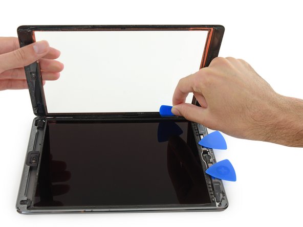
Use the flat end of a spudger to pry the LCD out of its recess just enough to grab it with your fingers.
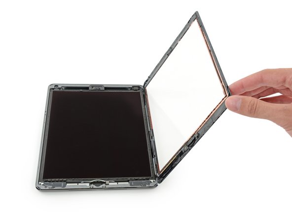
Flip the iPad LCD like a page in a book, lifting near the camera and turning it over the home button end of the rear case.
Be gentle and keep an eye on the LCD cables as you flip the display over.
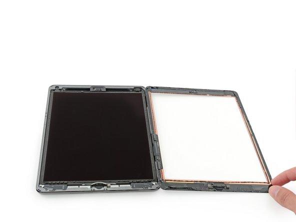
Lay the LCD on its face to allow access to the display cables.
Set the LCD down on a soft, clean, lint-free surface.
Use the flat end of a spudger to gently pry the display cable bracket straight up from the logic board.
The display cable connector is adhered to the underside of the bracket, so don’t push the spudger too far under the bracket, or you may damage the connector.
If the home button ribbon cable sticks to the iPad's rear case, don't try to force it. Gently peel it off the case using a pair of tweezers, and then you can fully remove the front panel assembly.
If you experience "ghost" or "phantom" touch input issues with your new display, this can be resolved by adding a layer of very thin insulating tape, such as Kapton (polyimide) tape, to the highlighted areas on the back of the panel. iFixit panels come with the proper insulation, and should not require the addition of any tape.
Without the proper insulation, these areas of the digitizer can ground out against other components, causing touch input malfunction.
The insulation is not visible to the naked eye, and is different from the foam dust barrier strips found on many iPads.
The following steps involve disconnecting many press connectors from their sockets on the logic board. When disconnecting these cables, be sure to pry up only on the connector, and not the socket itself.
Use the flat end of a spudger to disconnect the front-facing camera connector from its socket on the logic board.
Use the flat end of a spudger to gently fold the primary cellular antenna interconnect cable bracket up and out of the way.
The small, S-shaped interconnect cable remains attached to the bracket via a press connector on the underside of the bracket. If it disconnects accidentally, reconnect it by pressing it into place.
Use tweezers to carefully pull the upper button assembly ribbon cable straight out of its connector.
There is very little give on this cable, so you may need to apply a decent amount of force. Be sure you are pulling the cable straight back, and not upward against the connector.
Use a pair of tweezers to peel up the tape securing the right Wi-Fi antenna cable near the SIM board.
Peel carefully and pull up on the tape only—not the antenna cable, which will rip easily.
It may be helpful to fold the SIM board cable back slightly to better access the tape—but be careful not to damage the SIM board cable. If you need more clearance, remove the SIM board.
In the next steps, you will use an iOpener to apply heat to the rear case of the iPad to soften adhesive holding the logic board in place.
As you reheat and place the iOpener in each of the indicated locations, leave it in place for at least a minute to soften the adhesive through the rear case.
The adhesive is in the form of seven strips of black tape—refer to this step as you work at heating and prying to keep track of where each piece is located.
As you complete the next few steps, prying adhesive securing the logic board in place, always start by testing gently to see if the adhesive is softened. If not, reheat the iOpener and reapply it to the back of the rear case.
Carefully insert an opening pick under the logic board, between the front-facing camera and the battery.
Be sure to insert the pick over the the antenna cable that runs along the length of the battery.
Slide the guitar pick toward the front-facing camera connector, and stop at the bend in the logic board.
Insert a plastic card underneath the logic board at the battery connector.
Do not use excessive force when inserting this card under the logic board to prevent damaging its battery pins. If the logic board wont budge easily, try reheating the adhesive underneath with an iOpener.
As you push through the adhesive at the outer edge of the logic board, be careful not to damage the upper button assembly ribbon cable that you disconnected in Step 60. Position the card exactly as shown.
Slide the card all the way underneath the logic board, separating the adhesive along the outer edge.
Gently lift up on the logic board from its lower edge and remove the logic board.
When installing the logic board, check to make sure that each of the cable connectors you detached earlier is correctly routed over the top of the logic board before proceeding with reassembly.