简介
Flipper Zero is a portable multi-tool for pentesters and geeks in a toy-like body. It loves hacking digital stuff, such as radio protocols, access control systems, hardware and more. It's fully open-source and customizable, so you can extend it in whatever way you like.
你所需要的
-
-
The top shell, the IR cover and the acrylic window are one solid part and can't be disassembled. (They pop out with a bit of force but wont go back in as well without some sort of glue)
-
The Flipper Zero only uses two types of screws:
-
Long screw size is M1.7x8
-
Short screw size is M1.7x4
-
-
-
Eject the microSD card (if present) by pressing it with your fingernail.
-
-
在这个步骤中使用的工具:Phillips #0 Screwdriver$5.49
-
Use a PH0 screwdriver to unscrew the four long screws holding the back cover.
-
-
-
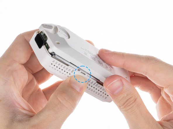
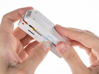
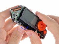
Press the middle of the top cover on both sides, one by one, to release the latches that hold the back cover in place.
-
Once the latches are released, you can remove the bottom cover.
You need to press a little stronger between the GPIO ports than next to the SD-card slot.
-
-
在这个步骤中使用的工具:iFixit Opening Picks (Set of 6)$4.99
-
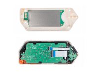
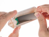
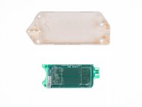
The board with the NFC antenna is glued to the bottom cover with adhesive tape.
-
To remove the board, gently pry one of the edges of the board with a plastic pick to peel off the adhesive tape.
-
-
在这个步骤中使用的工具:Phillips #0 Screwdriver$5.49
-
Use a PH0 screwdriver to unscrew the two short screws that are holding the chassis and top cover together.
When I did this I had a long screw and a short screw. The long screw was top left. Thanks for the excellent guide!
I also had 1 long and 1 short screw
-
-
-
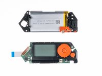
Take the chassis out of the case.
take the chassis out of the case... well alright... please explain how because it's very much stuck at the side of the USB port :/
2023 version is different than the 2022?remco katz - 回复
My case is unable to disconnect from the chassis
I found out... on some models there are another set of screw on the board with the screen. So you need to carefully remove the first board. Moving the orange plastic stuff helps. Also the boards will still be connected by the battery cable. So you will need to rotate one board over the other gently to access the 2 last screws... epic!
-
-
-
Disconnect the battery by prying the connector with a plastic pry tool and pulling it out.
-
-
在这个步骤中使用的工具:iFixit Opening Picks (Set of 6)$4.99
-
Disconnect the large ribbon cable from the board. Use a plastic pick to lift the latch up to release the locks.
-
-
-
Once the connectors are unlocked, carefully pull out the ribbon cables.
-
-
在这个步骤中使用的工具:Phillips #0 Screwdriver$5.49
-
Unscrew the short screw holding the iButton board in place using a PH0 screwdriver.
-
-
-
在这个步骤中使用的工具:Flathead 1.5 mm Screwdriver$5.49
-
To disconnect the flat cable from the iButton board, use a flat screwdriver to carefully release the lock by pulling the latch up, then pulling gently on the ribbon cable.
-
-
-
Once the connector is unlocked, gently pull the cable out of the connector.
-
-
-
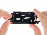
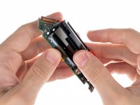
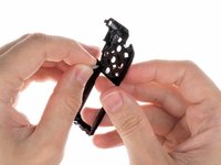
To release the battery chassis, gently rock it back and forth while pulling the two parts apart.
I'd say it's just a little more than a "gentle rock". There are two tabs. One is visible to the left of the display, through the PCB. The other is hidden under the buttons. I gently released the visible one by flexing it away from the display, and then the other came loose more easily with some gentle encouragement.
-
-
-
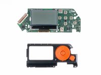
To remove the NFC RFID board, release it from the latches in the sequence shown.
-
-
-
Release the board from the latches by pressing on the edge of the chassis near the specific latch in the specified sequence.
-
-
-
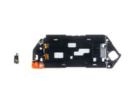
Take out the vibration motor.
-
-
在这个步骤中使用的工具:Phillips #0 Screwdriver$5.49
-
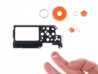
To remove the lace mount, use a PH0 screwdriver to unscrew the short screw that is securing it in place.
-
-
在这个步骤中使用的工具:iFixit Opening Picks (Set of 6)$4.99
-
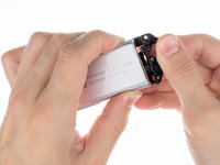
The battery is attached to the chassis with double-sided tape. To remove it, use a plastic pick to gently peel the battery off the chassis.
-
-
-
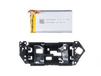
Remove the battery from the chassis.
This kind of battery is standard, as this device is not a known brand, you will not find a Flipper Zero branded spare part batteries, indeed, it's a standard no-name Li-Po battery that is being used in this device.
From the picture, we can guess this battery is a standard 3.7V Li-Po battery having a power capacity of 7.77W, so the capacity is indeed 2,1Ah -> so 2100 mAh of capacity.
Note : we can observe there is a circuit protection (BMS) on this battery, I don't know how this device reports voltage, temp and other battery-related stats but these features may not work properly if BMS of the new battery is not compatible with the device firmware.
After more research, I found the data sheet of this battery for you as the manufacturer of this device made public a lot of hardware related docs : https://cdn.flipperzero.one/FLIPPER_ZERO...
I found dimensions are specified in it with other useful information. So I don't know which dimensions you are searching for, there are mentions on page 4 of this doc
Brendan -
There is also additional dimensions specified page 5 and also pictures starting page 22.
This document has been made by the chinese laboratory in charge of thesting the safety of the battery used in the flipper zero device.
Brendan -
-
-
在这个步骤中使用的工具:iFixit Opening Picks (Set of 6)$4.99
-
Use a plastic pick to lift the latch up to unlock the connector.
-
-
在这个步骤中使用的工具:Phillips #0 Screwdriver$5.49
-
Unscrew the two short screws holding the button chassis using a PH0 screwdriver.
-
-
-
To disconnect the button chassis and the board, press the latch on the side shown below.
-
-
在这个步骤中使用的工具:iFixit Opening Picks (Set of 6)$4.99
-
Disconnect the screen ribbon cable from the board. Use a plastic pick to lift the latch up to open the lock.
-
-
在这个步骤中使用的工具:Flathead 1.5 mm Screwdriver$5.49
-
Release the latches with a flat screwdriver. You need to be careful with the springs under the buttons.
-
-
在这个步骤中使用的工具:Flathead 1.5 mm Screwdriver$5.49
-
Use a flat screwdriver to release the light guide from the chassis.
-


14指南评论
Agree with Evge, when I read "PH0" I picked mine but they wouldn't quite fit. I had to use a PH1 (1.2 to be exact, according to toolset casing) to be able to unscrew the chasis and get to the battery (I had to only remove and plug back the battery cable to fix my problem)
Careful with those screws. They are not great quality and strip easily.
Yeah, I have run into the same issue. The screw securing my IR/iButton board sheered in half! I cant remove the bottom part since its flush with the socket, but the board seems to be alright without it and is still in place since the chassis supports it. I still need to find a way to get it out :)
SkidFace -
Second that about the screws being low quality. Also, if your FZ battery decides it doesn't like you anymore (it shows some 50%ish max), open it (steps 1-4), disconnect it (steps 7-9), and reconnect the battery. And it seems to be something that's gonna be routine, because it happened back in October and again now in December.
When disassembling this time I checked the screws better, and it seems a 2.0 phillips is the best fit for the long screws.
Am I the only one that ended up with 5 long screws?
My small iFixit toolkit doesn't have the right bits for step 3. PH0 strips the slot on the screw, and PH1 does not fit into the hole. If you have the same tools as me, don't force it, you'll do damage to the screws. Try other screwdrivers.
The IR cover does come out, just pull
there are three golden pins that fall out when you open the clamshell. this doesnt show them or where they go. fml.
Those pins are supposed to be attached to the IR board, you have accidentally broken them off in the disassembly, they can only be soldered back on with a soldering iron/hot air station. You can also just leave them in their respective holes and the press of using the pins, will make them make contact with the board, they will just be loose. Or leave them out entirely, iButton isnt too common in most countries.
Francis -
what do i buy to replace gpio pins 1-8?
What about the wifi module? Is it possible to fix it? I have this kit https://www.sdrstore.eu/software-defined... and the wifi board stopped working after 2 months. Is there any way I can fix it?