简介
Follow this guide to replace the joysticks on a Sony PlayStation 5 DualSense controller.
你所需要的
-
-
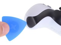
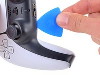
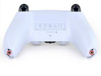
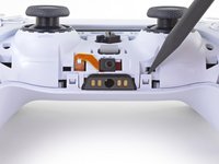
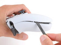
Insert an opening pick underneath the middle trim at the bottom-right corner of the controller to release the clips securing it to the case.
-
-
-
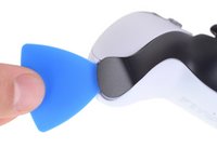
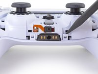
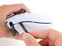
Slide the opening pick along the lower-right edge of the middle trim to release the clips securing it to the case.
-
-
-
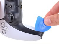
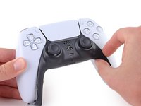
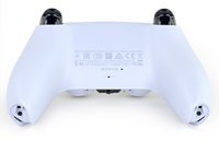
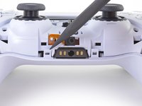
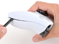
Insert an opening pick underneath the middle trim at the bottom-left corner of the controller to release the clips securing it to the case.
-
-
-
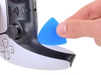
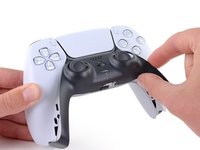
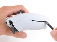
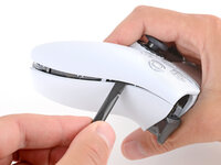
Slide the opening pick along the lower-left edge of the middle trim to release the clips securing it to the case.
-
-
-
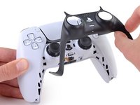
Use your fingers to lift up the bottom edge of the middle trim to release the remaining clips.
-
Lift the middle trim over the joysticks to remove it.
-
-
-
With one hand, grip the controller and use your thumb to hold down the left trigger.
-
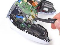
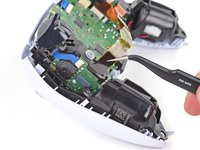
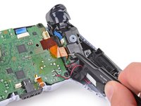
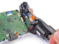
With your free hand, insert the flat end of a spudger between the L1 and L2 buttons.
-
Use the spudger to gently pry the L1 button away from the controller and remove it, holding your finger over the button so it doesn't eject.
Tried prying from the front of the buttons as pictured and my spudger broke off in the gap. A video I watched showed them being pried off from the back (between the R1/R2 and L1/L2 buttons) which seemed much easier.
Agree with Lora's comment above. I was able to use an old credit card to take L1/R1 out this way. I pressed down the L2/R2 button to create space to work in, then came in from between L1/L2 and R1/R2. It's easy to pop one of the outer corners first then you can work the credit card around the top and the rest falls out.
-
-
-
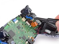
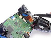
Repeat the previous step to remove the R1 button.
What I didn't see addressed anywhere (here or in other similar articles) is that replacement R1 / L1 buttons can be differ enough to be un-usable depending on which model your ps5 controller is. The ones I ordered don't fit and now I can't find a way to be sure I get the right ones because few know there's even a difference.
Did you already figured it out? The version the we need yo use?, We are in the same situation here.
Tried prying from the front of the buttons as pictured and my spudger broke off in the gap. A video I watched showed them being pried off from the back (between the R1/R2 and L1/L2 buttons) which seemed much easier.
-
-
-
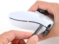
Use a Phillips screwdriver to remove the two 6.4 mm screws securing the bottom corners of the lower case.
-
-
-
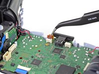
Use the point of a spudger to release the two clips on either side of the headset jack.
-
-
-
-
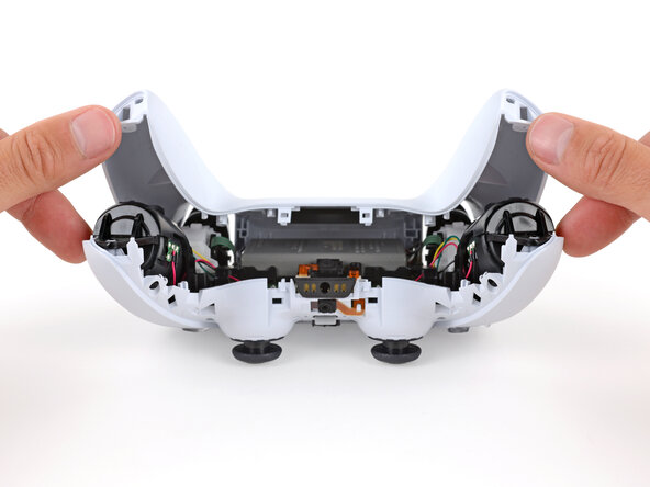
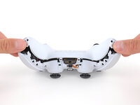
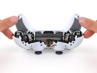
Remove the rear case.
There are four more clips/hooks hidden in the seams along the outer sides of the handles. If you pull open the controller as shown in this step, then you will shear off the two tiny clips which are right next to the R1 and L1 buttons.
Therefore, you should first release those clips by prying the seams open sideways.
I noticed this with the updated design of the controller, not sure whether the hooks are present on the first version.
The hooks are not critical for the integrity of the controller as the two halves are held together by the screws hidden under the buttons. The damage does show that the controller has been taken apart.
Thought I'd clarify: The clips next to the L1 and R1 are on the outer side from the L1 and R1 buttons, I'd suggest zooming in on the picture to see them. They're quite easy to break, but also easy to remove using the plastic spudger along the seam, bending the bottom cover outwards
I am still strugling to find the clips. Could someone point them out in the image with a screen shot or something like that.
I keep getting stuck at this step too with the new DualSense CFI-ZCT1WA revision. The top and bottom shells seem like they are fused together next to L1/R1 but I can't seem to be able to find where these hidden clips are located. My controller is still in warranty so I don't want to break them in case I can't fix my issue.
but also easy to remove using the plastic spudger along the seam, bending the bottom cover outwards
I tried this but it seems that the you need a lot of force and I ended up bending the tip of my spudger. Are you sure it's not the top cover that you need to pry away? The bottom cover has a ridge to make sure it's under the top cover so it's not easy to bend outwards.
@samomio I think there needs to be a step added for these new clips.
Ok, not seeing a lot of motion on this request, so I've uploaded photos of the hooks to imgur.
Here ya go: https://imgur.io/a/7NWmQi5
This guide really needs an update on this. I had a really hard time getting the forward clips to release even after referring to the comments above. Pretty sure I broke them in the end. No big deal but would be great if the iFixit experts could work out a good method for releasing them.
I finally figure it out!!
The hidden clip is very tricky but once you understand how it works it is easy to remove.
Use Sean's picture: https://imgur.io/a/7NWmQi5
What sean is showing, is actually the bottom shell of the seam.
To disassemble
1. Use the flat side of the spudger, pry the bottom seam OUTWARDS near the R1/L1 button hole.
2. (most important) While prying the bottom shell seam outwards, push your thumb on the upper shell and push outward as well (you can do this by applying pressure from the removed R1/L1 button hole towards the seam. And then it will disassemble automatically
And that's it!
updated instruction:
I finally figure it out!!
The hidden clip is very tricky but once you understand how it works it is easy to remove.
Use Sean's picture: https://imgur.io/a/7NWmQi5
What sean is showing, is actually the bottom shell of the seam.
To disassemble
1. Use the flat side of the spudger, pry the bottom seam OUTWARDS near the R1/L1 button hole.
2. (most important) While prying the bottom shell seam outwards, hold your thumb on the upper shell as anchor and then use your other finger to pry the bottom edge of the controller up away from the shell. If you are doing the first step, then don't worry about breaking the clip, just force it open. And then it will disassemble automatically
And that's it!
Yes! Thanks a bunch Penn. That did the trick! Much appreciated
Sean -
I managed to do it just by pulling harder than what I was already doing. And I don't think I broke anything. So, for me at least, the technique described in this guide worked.
The video linked below clearly shows how to open the controllers with the extra clips near the L1/R1 areas.
See a video here by How To X on YouTube... https://youtu.be/djIvRoclr_E?si=dKFpQCZe...
I really struggled with releasing the rest of the back panel (close to the shoulder buttons.) What finally seemed to do the trick for me, was doing both sides at once with upward turning motion of the back panel with the shoulder buttons approximately at the axis. Trying to release just one side and then the other felt impossible without potentially breaking the case.
This was what did it for me
-
-
在这个步骤中使用的工具:Tweezers$4.99
-
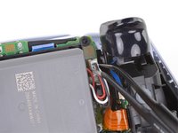
Use a pair of tweezers or your fingers to disconnect the battery from the motherboard.
Tweezers aren't gonna grip that the way you need.
For those having trouble using tweezers to pull out the connector, you can grab below the lip of the connector and use the controller as a lever to pull it up as seen here DualSense Controller v2 Battery Replacement
This little trick helped me so much and I believe it should be shown on this guide as well.
-
-
在这个步骤中使用的工具:Tweezers$4.99
-
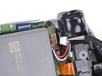
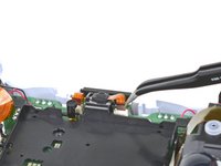
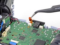
Grab the lower microphone ribbon cable pull tab with your fingers or a pair of tweezers and disconnect it from the motherboard.
These ribbon cables have small tabs on either side you can use to help pull out the cable. You can slightly pull up, alternating between the two sides, to slowly wiggle the connector out.
I tried to use metal tweezers to pull this out and absolutely shredded the ribbon in the process. It's just a microphone so I wouldn't expect it to matter but now none of the games get any input from the controller even though the controller works fine in the home menu 🥲
Probably just use your fingers if you have the dexterity for it.
As others have said, try to only remove the ribbon and not the white connector. I'd advise holding down the white connector with something (perhaps your prying tool or finger) as you pull the ribbon out gently with the tweezers.
Best to avoid pulling out the white connector if possible - but its not the end of the world if you do accidentally pull it out, as I did. You can put the connector back in but you need to be very precise with the alignment over the 6 pins it connects to on the circuit board. I had to use a magnifying glass and it took me a few attempts. -
-
-
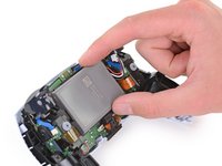
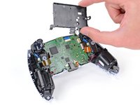
Use a Phillips screwdriver to remove the 6.4 mm screw securing the battery bracket.
-
-
-
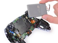
Lift the battery bracket out of the motherboard.
Black and red wires fit neatly under the lower left and lower right arms of the battery bracket, to avoid potential damage when reconnecting the rear case.
This needs to be noted. Thanks!
-
-
-
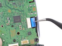
Grip the right trigger assembly ribbon cable pull tab with a pair of tweezers or your fingers and pull up to disconnect it from the motherboard.
If your cables are blue and in a different position, don't sweat. It's all good. Just do the same as they do and if you feel it is necessary, label with a sharpie left and right on each cable. A simple L and R works for this case
Qbert 2030 - 回复
-
-
-
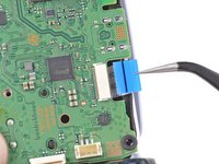
Grip the right trigger assembly ribbon cable pull tab with a pair of tweezers or your fingers, and pull up to disconnect it from the trigger assembly.
-
Remove the ribbon cable.
Depending on the revision of your controller, these ribbon cables may be slim and white and if you remove it completely, you might have to remove and tear down the trigger assembly to get the ribbon cable back in.
maybe I'm missing something but in this case it doesn't seem to me like these cables need to be outright removed.
-
-
-
Grip the left trigger assembly ribbon cable pull tab with a pair of tweezers or your fingers and pull up to disconnect it from the motherboard.
-
-
-
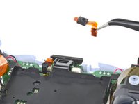
Use a pair of tweezers or your fingers to grip the upper microphone ribbon cable pull tab, and pull up to disconnect it from the motherboard.
-
-
-
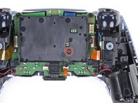
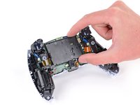
Use a pair of tweezers or your fingers to grip the touchpad ribbon cable pull tab, and pull it straight out of the motherboard connector.
-
-
-
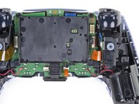
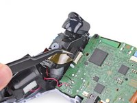
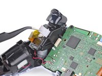
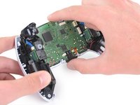
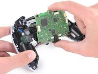
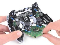
Carefully guide the joysticks through the front case and lift the motherboard out.
My motherboard wouldn't just lift right out. So I noticed there's also a pair of barely visible small black clips, one on each side of the motherboard, holding it down. One is right beside the battery connector and the other's directly across on the opposite side of the motherboard right beside the ribbon cable connector.
Such a good observation!
zidek22 -
That helped a lot. If you can push those tabs it comes out a lot easier. I used my tweezers to push the left one and then as others had said pushing on the joysticks from the front of the controller makes it much easier.
Fruke -
Just push on the sticks. Pops out like a charm, zero effort.
-
-
-
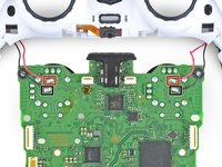
Flip over the controller and motherboard.
-
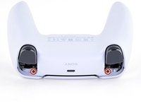
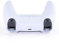
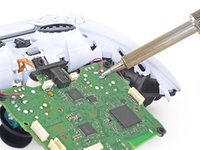
Use a soldering iron to desolder the vibration motor wires from the motherboard:
-
Two red wires
-
Two black wires
but how do I solder them back and at what temperature. I’m a kid that’s why i’m asking. Also should i wear gloves . My controllers black wire disconnected so this is why i’m asking and yes i know how to do it and i will be supervised. I watch I Tronics fix’s videos so i’ma a big fan of him and all i know about this kind of stuff is from him.
The temperature will depend on the solder and tip you are using. Start at 180°C (360°F) and increase temperature as needed.
—
To solder the wire back on:
1. Place the end of the wire on the solder pad on the motherboard. Use something to hold it in place while you work, like helping hands.
2. Heat up your soldering iron and touch the tip to the solder pad for 15-30 seconds to get it hot.
3. With the soldering iron and wire touching the pad, use the tip of your soldering iron to melt just enough solder to cover the wire and pad. Remove the solder and soldering iron tip as soon as enough solder melts onto the pad.
—
Wearing gloves and safety glasses is a good idea if you’re new to soldering, and practice on something else first. Read our soldering guide before you start too.
What if I want to leave the vibration motors out? Is there anything special that has ti=o be done?
In addition to the 2 red and 2 black wires, my controllers also have 2 yellows and 2 greens. So 8 wires total. I'm going to remove all of then and then install in reverse order. Wish me luck!
Dieser Schritt wirt einfach unmöglich ich habe für 2 Stunden damit vergeblich gekämpft auch nur eines der Kabel zu lösen. Und das mit meinem Lötkolben auf 450°C. Wie es mit "optimierten" ent-löt tools aussieht konnte ich nicht testen, da ich es vermutlich für immer aufgeben werde Dinge die Löterfahrung benötigen zu repairieren.
Kurz gesagt, versucht diese Reparatur garnicht erst, wenn ihr nicht SEHR viel erfahrung habt. Kauft euch lieber einen pre-gemoddeten Kontroller (was ich jetzt vermutlich machen werde). -
-
-
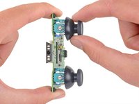
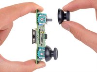
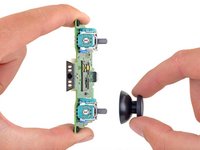
Pull the joystick covers straight off the joystick assemblies.
-
Only the motherboard remains.
-
-
在这个步骤中使用的工具:Desoldering Pump$3.99
-
Use a soldering iron and desoldering pump to desolder the fourteen connections on each joystick.
Another method is to use a heat gun and some Chipquik removal alloy.
You'll need a heat gun, some Chipquik removal alloy/solder, and a soldering iron. Add removal alloy to the soldering joints so it is mixed with the existing solder. Put your heat gun on high heat and low pressure (prevents dislodging other SMT components), and hold it ~1cm over the solder joints. Maintain a low and constant force to pull the joysticks out while holding the heat gun over the joints; once the heat gun melts the solder, the joystick can be carefully pulled out. You can also use the soldering iron to push the joystick's pins down and out to help remove the joystick. It should take less than 10 minutes per joystick.Für mich war das Entlöten mit einem normalen Lötkolben unmöglich (bin allerdings auch Anfänger auf dem Gebiet a.k.a. war mein erstes Mal). Für mich war eine Heißluftpistole (400 Grad) die Erlösung - damit viel der Stick innerhalb von wenigen Sekunden wie von selbst heraus und ich musste nur noch die Löcher der Platine reinigen.
danke für das hinzufügen der Temperatur! sind keine Komponenten verbrannt?
mahanako -
You can't unsolder the stick module with just a soldering iron, you need a heat gun. A soldering iron alone is not enough to heat all connections at once, wich is necessary to remove the module. Heating connections one by one will result in the remvoal of only a part of the solder, you won't be able to free the pins from the holes because a little bit of metal will stay out of reach.
This is a joke, right? It is ^#(


To reassemble your device, follow the above steps in reverse order.
Take your e-waste to an R2 or e-Stewards certified recycler.
Repair didn’t go as planned? Try some basic troubleshooting, or ask our Answers community for help.
To reassemble your device, follow the above steps in reverse order.
Take your e-waste to an R2 or e-Stewards certified recycler.
Repair didn’t go as planned? Try some basic troubleshooting, or ask our Answers community for help.
48等其他人完成本指南。

26条评论
How do you differentiate a real joystick part from fake ones? Since in my situation i can't order straight from sony.
I would suggest getting a PS4 Dualshock controller from the classifieds since there's a pile of them available for cheap and take the analogue stick from there.
Thanks for the tutorial! I wonder if anyone has a problem after replacing the joystick? The controller simply won't turn on. If I connect the controller to either ps5 or my pc via usb, it will blink 3 times in orange and turn off. If I press the PS button when connected with usb, it will also blink orange 3 times and nothing happens. I've tried hard reset by using the hole on the back but it didn't help. Any advice??
How do I calibrate afterwards? I changed the sticks, but they need calibration.
I bought replacement sticks from GuliKit and they link to a third-party calibration tool that worked for me!
Hello my controller wont start or charge after resoldering new joysticks any suggestions?
Thanks
Hello, I have soldering Iron and pump but am having trouble removing the tiny of amount solder around the connections. any advice?
heat gun, heat it up for about 5-10 min and the new module should snap right in
Another option when trying to clean up the old solder to open up the through-holes is to use solder wick. I found that sometimes it helps to add a bit of your own solder first in order to be able to wick up the rest.
Could I possibly only replace the potentiometer instead of unsoldering the entire unit?
I broke my joystick R2 controller this can be repaired?
Devi Shree - 回复
Great guide! I successfully replaced my joystick and it works perfectly. Definitely need a good solder iron, flux and a desolder pump.
there is differemce between ps4 and ps5 controller potentiometres...one is 2kOhm and one is 10kOhm so swappimg to another will make ur calibrations out of whack...so in theese comments people recommended ps4 sticks as replacement but those values would cause it to go out of whack....is there way to calibrate it without modboard or additional pot?
Thanks for the guide! Definitely helped me out. I just wanted to add a comment because I think I have a different (possibly newer) version of the controller with a couple of small differences:
1. Starting in step 17, there are still four main ribbon cables to disconnect from the board, but they look slightly different and the ones on the sides of the board are narrower.
2. In step 24, there are two additional pairs of wires, 2 yellow and 2 green. They require the same steps as the black and red wires and there's even a Y on the board indicating which pad is for the yellow wire. Just desolder them and resolder them when you're done and you'll be good to go!
this is a little off from the norm but do
they make an adapter for the analog sticks so they can be flipped like a victrix controllers
Grazieeeeeeeee
I've been practicing desoldering these things on old junk controllers while I wait for my joystick replacement to arrive and I've noticed I just can't seem to get all the solder out and so far, even using a solder wick. I can get it to a point where all the prongs look entirely clean, but the stick won't come out and I'm afraid of the fumes from melting the plastic by working on the other side of the board.
Hallo ich habe eine Frage und zwar habe ich meine analog Sticks ausgelötet und danach alles mit Isopropanol gereinigt . Danach hab ich den neuen Hall Effekt Stick eingelötet und die Platine an einem gamepad Tester getestet.
Nach links und rechts steht der Stick perfekt nahezu auf null aber nach oben und unten steht der Stick auf Achse -1 und reagiert gar nicht.
Was hab ich da falsch gemacht?
kann man auch die sticks in den modulen tauschen oder sind dazu andere nötig?
Thanks for the guide. Could you add a note to the PCB removal section about the rubber hole liners in the four corners of the PCB? They fall out easily and I just narrowly avoided losing one.
I also found a solder sucker to be ineffective. I used a hot air rework station set to 450f while pulling gently on the joystick to be removed and it came out peacefully after about 45 seconds. After that I used solder wick to clean up the holes. It’s not a tool that most people will have, though there are cheap ones on Amazon, but I wouldn’t have been successful without it.