跳转到主内容

当前版本的文档还未经巡查,您可以查看最新的已查核版本

你所需要的

  1. , 检修门: 步骤 1 中的图像 1,1
    • 松开检修门上唯一一颗十字螺丝。

    • 这个螺丝固定着检修门。

    • 从iMac上移开检修门。

  2. , 玻璃面板: 步骤 2 中的图像 1,2 , 玻璃面板: 步骤 2 中的图像 2,2
    在这个步骤中使用的工具:
    Heavy-Duty Suction Cups (Pair)
    $14.95
    购买
    • 玻璃面板固定在前外壳上,周围有十四个磁铁固定。

    • 在玻璃面板的对角线上吸上两个吸盘。

    • 要使用吸盘吸的牢固,首先将吸盘可以活动的把手移动使其与玻璃面板平行。 在轻轻地将吸盘保持在玻璃上的同时,抬起活动手柄直到与另一个手柄平行。

    • 如果您的吸盘无法吸上,尝试使用温和溶剂例如Windex来清洁玻璃面板和吸盘。

  3. : 步骤 3 中的图像 1,1
    • 小心,竖直的从iMac上提起玻璃面板。

    • 玻璃面板周围有几个定位销。 为了避免将玻璃面板上的这些针脚弄坏,请务必在拆卸过程中竖直向上拉动。

    • 在重新安装之前,请务必仔细清洁LCD和玻璃面板的内部面板,因为当显示屏打开时,你不想被任何指纹或灰尘所困扰。 将玻璃平面放置在干净的铝箔表面上是保持清洁的最好方法。

  4. , 外圈: 步骤 4 中的图像 1,1
    • 移除将后壳与外圈固定的12颗螺丝。

    • 8颗13mm T8 梅花螺丝。

    • 4颗25mm T8 梅花螺丝。

  5. : 步骤 5 中的图像 1,1
    • 断开麦克风线缆连接插头,如果有必要的话移走胶带。

    • 要确保挡板正常,请确保将麦克风电缆和连接器插入相机板旁边的空白处。

  6. 这个步骤还没有翻译 帮忙翻译一下

    : 步骤 6 中的图像 1,2 : 步骤 6 中的图像 2,2
    • When reassembling the bezel:

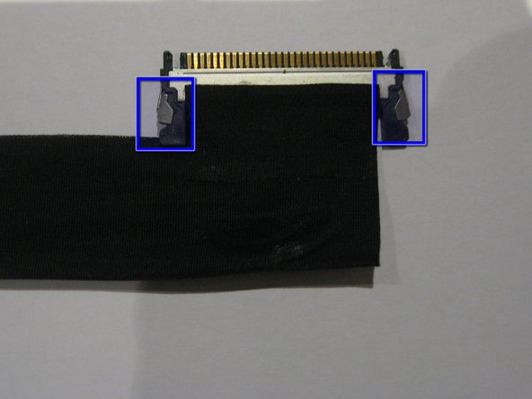
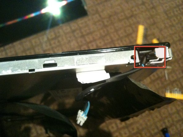
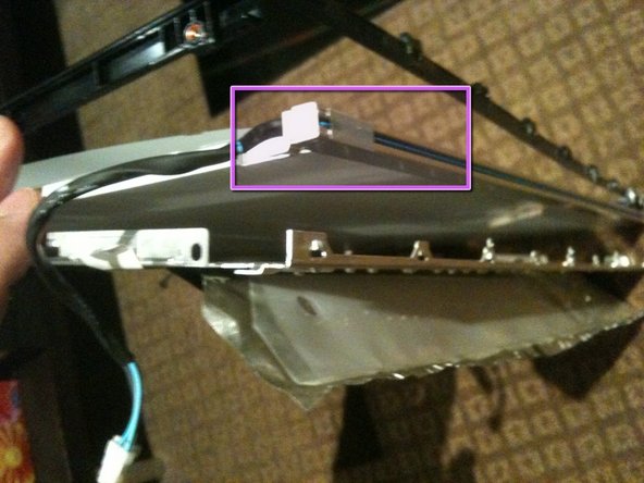
    • be sure to tuck the microphone cable and connector into the void next to the camera board.

    • Gently guide the microphone connector and cables through the ±1in long slot at the right of the iSight camera. Once the bezel is properly assembled, gently push the microphone connector and cable into the bezel through that slot.

  7. , 显示面板: 步骤 7 中的图像 1,2 , 显示面板: 步骤 7 中的图像 2,2
    • 从逻辑板上径直拉起LCD温度传感器的连接插头。

    • 如果有必要,请将LCD温度传感器电缆从逻辑板背面取下。

    • 当您取出LCD时,请检查LCD温度显示电缆的布线。 重新安装显示屏时,请确保此电缆未阻塞前挡板的底部的一个螺丝。

  8. : 步骤 8 中的图像 1,1
    • 移除两颗将显示数据线缆固定在逻辑板上的5.3mm T6 梅花螺丝。

  9. : 步骤 9 中的图像 1,1
    • 使用插头上面的黑色拉手来将插头从逻辑板上拉离。

  10. : 步骤 10 中的图像 1,2 : 步骤 10 中的图像 2,2
    • 移除8颗将显示面板与后壳固定的12mm T8 梅花螺丝

    • 从显示屏左侧提起显示面板,并将其向iMac的右边缘旋转。

  11. : 步骤 11 中的图像 1,2 : 步骤 11 中的图像 2,2
    • 当提起显示面板的时候,断开四条变频器电缆。

    • 在重新安装时,将四个变频器电缆连接器放置在连接到后面板的组件之间的空隙中,以使显示面板齐平。

    • 在重新组装时,变频器电缆的顺序可在每个插座内互换。

    • 如果要更换硬盘,需要额外的帮手,来以进入内部并取出硬盘,而不必断开上一步中的LCD温度和显示连接器,只需将LCD支撑起来。

  12. 这个步骤还没有翻译 帮忙翻译一下

    : 步骤 12 中的图像 1,3 : 步骤 12 中的图像 2,3 : 步骤 12 中的图像 3,3
    • The rest of this procedure should be done in the cleanest possible work environment to avoid dust getting BEHIND the LCD (I learned this the HARD way!)

    • Once the LCD panel is removed you need to peel back the black foil from the top edge of the LCD to reveal the clear plastic PCB protector.

    • Now gently peel the clear plastic PCB protector off the top edge. Make sure you don't damage the flex cables attached to the PBC you are exposing.

    • There are a total of 8 flex cables along the top edge

  13. 这个步骤还没有翻译 帮忙翻译一下

    : 步骤 13 中的图像 1,3 : 步骤 13 中的图像 2,3 : 步骤 13 中的图像 3,3
    • Use a sharpie or similar, mark the side brackets on either side of the LCD panel before removing screws as they are different

    • Use a T10 Torx driver to remove the 2 screws from each side bracket (total 4 screws)

  14. 这个步骤还没有翻译 帮忙翻译一下

    : 步骤 14 中的图像 1,3 : 步骤 14 中的图像 2,3 : 步骤 14 中的图像 3,3
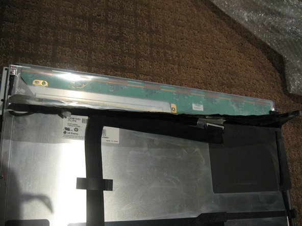
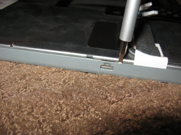
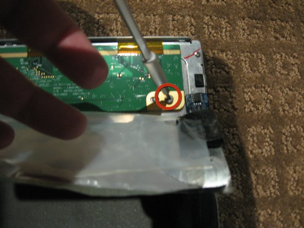
    • Stand the LCD panel on its TOP edge and locate the lock tabs along the BOTTOM edge. There are 5 along the length of the bottom edge

    • Use a flat blade driver or metal spudger to Gently pop the bezel off the lock tabs.

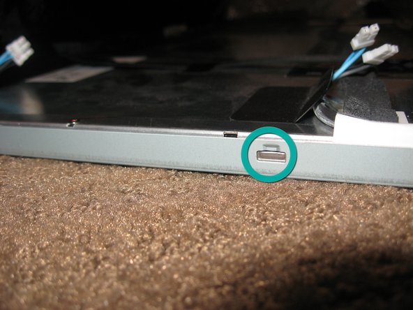
    • Locate the lock tabs on either side of the LCD panel. There are 2 on each side

    • Use a flat blade driver or metal spudger to Gently pop the bezel off the side lock tabs.

  15. 这个步骤还没有翻译 帮忙翻译一下

    : 步骤 15 中的图像 1,3 : 步骤 15 中的图像 2,3 : 步骤 15 中的图像 3,3
    • Now gently separate the metal bezel from the main body of the LCD panel

    • Lay the LCD panel down on with viewing side UP and remove the metal bezel

    • Make sure you are careful when removing the bezel from the TOP edge as you will be exposing the 8 flex cables mentioned in step 1.

    • Note the 3 flex tabs on the left edge

    • Do not damage any of the tabs or flex cables as these are the Row and Column Drivers. Damage to these will will cause faults like vertical/horizontal lines or white screen etc.

    • WARNING - Once the bezel is removed the LCD is LOOSE in the black plastic frame - only held in by the small gasket underneath.

  16. 这个步骤还没有翻译 帮忙翻译一下

    : 步骤 16 中的图像 1,2 : 步骤 16 中的图像 2,2
    • Using a plastic spudger or pry tool, work GENTLY around the edges of the LCD to loosen it from the gasket below - use GREAT CARE so you don't crack or chip the panel as it is only a couple mm thick

    • Once the LCD is loose you need to HOLD it in place in the black plastic frame and GENTLY flip the entire assembly so the LCD is flat on the work surface

  17. 这个步骤还没有翻译 帮忙翻译一下

    : 步骤 17 中的图像 1,2 : 步骤 17 中的图像 2,2
    • Remove the tape securing the LVDS cable

    • Press IN the 2 silver spring loaded catches on either side to release the cable and gently extract it from the connector

  18. 这个步骤还没有翻译 帮忙翻译一下

    : 步骤 18 中的图像 1,2 : 步骤 18 中的图像 2,2
    • Peel the back Black foil and clear plastic PCB protector to fully expose the PCB that runs across the top of the LCD assembly

    • Remove the 2ea Philips head screws from each end of the PCB

    • The PCB actually has a 3rd screw hole in the centre of the board. Perhaps my assembly is missing a screw

  19. 这个步骤还没有翻译 帮忙翻译一下

    : 步骤 19 中的图像 1,2 : 步骤 19 中的图像 2,2
    • Gently flip the PCB over 180deg so it is off the aluminum back panel.

    • Be CAREFUL not to damage the 8 flex cables

    • The PCB may be attached to the aluminium by some adhesive near the LVDS connector. IF so use a plastic pry tool or spudger to GENTLY lift the PCB up

    • Now lift the the back panel off the LCD separating the LCD from the back light assembly

  20. 这个步骤还没有翻译 帮忙翻译一下

    : 步骤 20 中的图像 1,3 : 步骤 20 中的图像 2,3 : 步骤 20 中的图像 3,3
    • Disassembling the back-light assembly is a little fiddly as there are a number of parts that all want to come apart at the same time

    • Remove the 6 Philips screws from the rear of the back light assembly

    • Removing the white tape from the CCFL cable.

    • Un-clip the CCFL cable from the black plastic surround

    • There are 2 CCFL cables and the process is essentially the same for each

  21. 这个步骤还没有翻译 帮忙翻译一下

    : 步骤 21 中的图像 1,3 : 步骤 21 中的图像 2,3 : 步骤 21 中的图像 3,3
    • Separate the black plastic surround from the aluminum back plate to access the CCFL tube assemblies

    • Start by un-clipping the tabs along the top edge of the assembly. There are 4 tabs along the top

    • The top CCFL tube can be seen and CAREFULLY removed

  22. 这个步骤还没有翻译 帮忙翻译一下

    : 步骤 22 中的图像 1,3 : 步骤 22 中的图像 2,3 : 步骤 22 中的图像 3,3
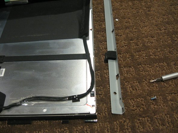
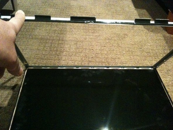
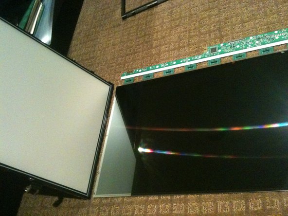
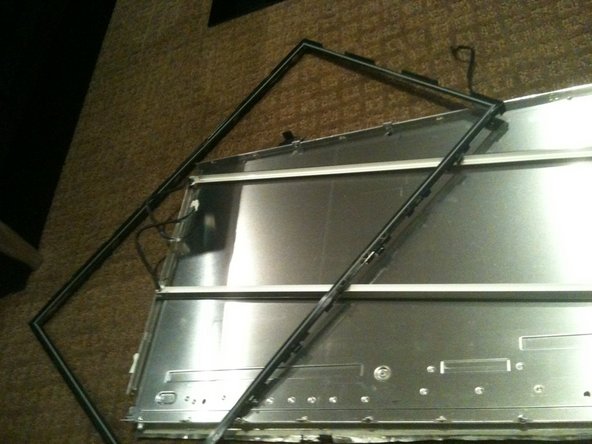
    • The bottom of the black surround can now be un-clipped and the entire surround removed

    • There are 4 tabs along the bottom of the assembly

    • Once the black surround is off the rest pretty much comes apart with the bottom CCFL tube being able to be removed in a similar manner to the top

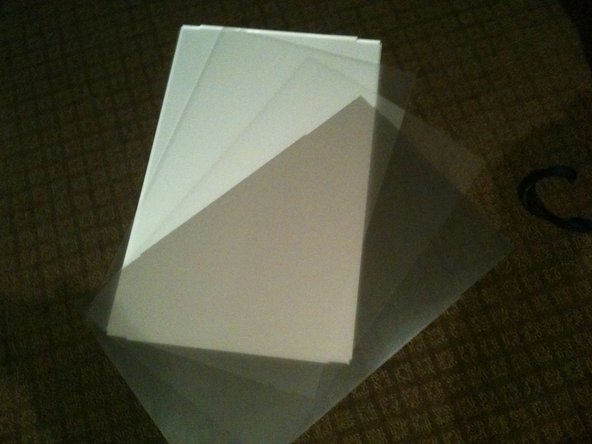
    • The centre of the back light assembly is made up of 4 main parts. A perspex sheet with white plastic coating, 2 opaque matt plastic sheets, and 1 Pearlescent matt plastic sheet

    • The plastic sheets are polarisers so need to be kept clean and free of dust and scratches

  23. 这个步骤还没有翻译 帮忙翻译一下

    : 步骤 23 中的图像 1,3 : 步骤 23 中的图像 2,3 : 步骤 23 中的图像 3,3
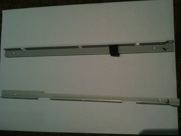
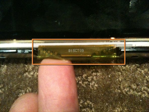
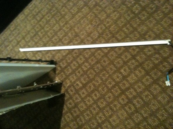
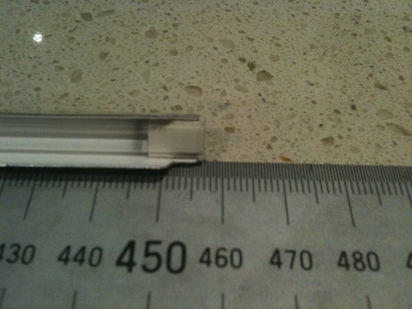
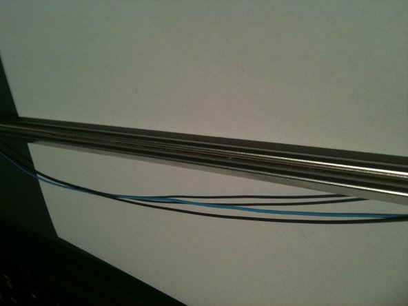
    • The CCLF tube assemblies are made up of a U shaped reflector with 2ea individual tubes inside. The entire assembly is 457mm long and 7.6mm wide. There are no part numbers on the assembly however there is a S on the end with the wires attached and an 18 on the other end.

    • The 2 CCFL tubes are held together with a figure 8 rubber band in the middle of the reflector so both tubes must come out at the same time.

    • The individual tubes are 448mm long (excluding the terminals - standard way to measure is end of glass to end of glass) and are 2.4mm diameter.

    • The CCFL are soldered to the wires so not a simple plug in replacement

    • The CCFL are EXTREMELY fragile so ensure you dont break them when installing them.

    • The CCFL reflectors are a tight fit over the sides of the perspex sheet and the other layers of plastic. Patience and a plastic spudger or pry tool should get you there

    • The closest I can find to my CCFL measurements are either the 446mm x 2.4mm or the 450mm x 2.4mm so I'd suggest the 446mm is used

    • See the Removing CCFL from iMac 20in LCD CCFL assembly guide for details

  24. 这个步骤还没有翻译 帮忙翻译一下

    : 步骤 24 中的图像 1,3 : 步骤 24 中的图像 2,3 : 步骤 24 中的图像 3,3
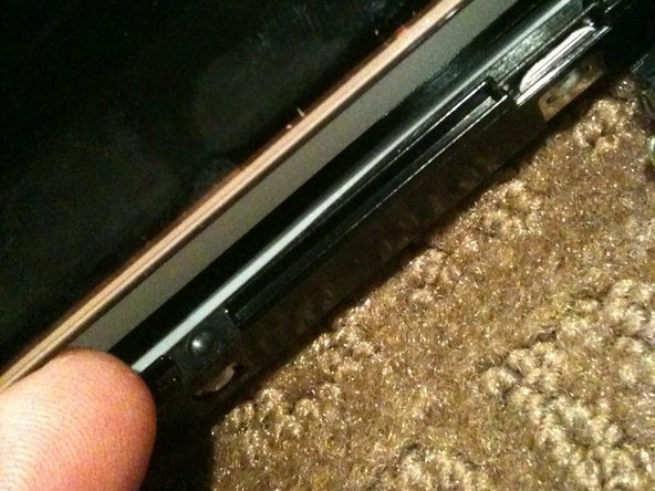
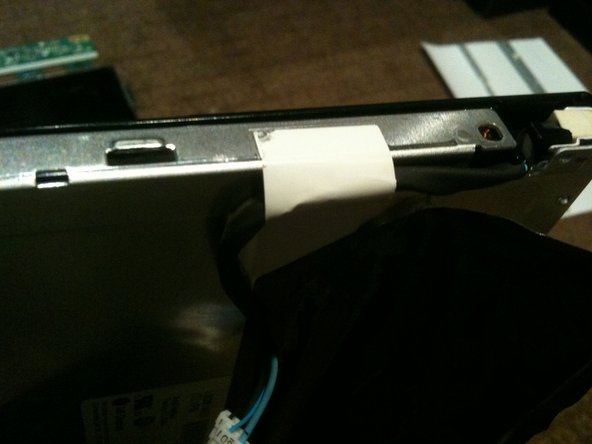
    • Remove the white tape from either end of the rear of the CCFL assembly.

    • Carefully remove about 15-20mm of heat shrink from the CCFL cable to allow the end cap to be removed, making sure you DO NOT cut or nick the wire insulation.

    • The wires have a HIGH VOLTAGE applied during operation and the insulation may break down if damaged causing a short

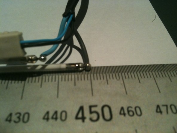
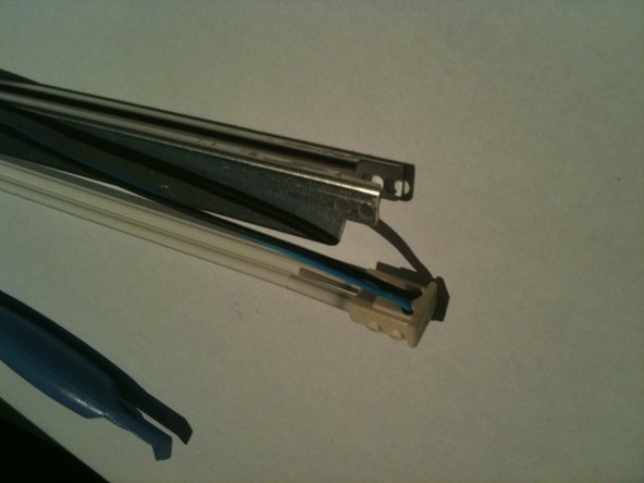
    • While holding the assembly, slowly and gently pull the THICK wires up and out of the slots in the white rubber cap.

    • Pull the wires one at a time ensuring you don't flex the CCFL and break it.

    • This will reveal the pins and solder joints.

  25. 这个步骤还没有翻译 帮忙翻译一下

    : 步骤 25 中的图像 1,3 : 步骤 25 中的图像 2,3 : 步骤 25 中的图像 3,3
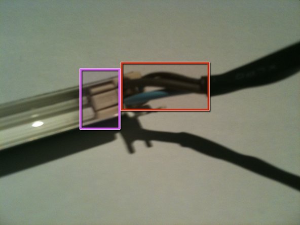
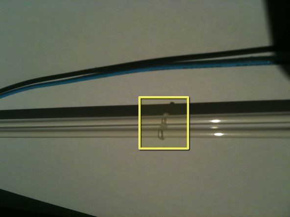
    • Gently push the THIN wires through the rubber end cap to create a bit of a loop on the rear of the assembly.

    • Using a plastic pry tool you can pop the rubber end cap out and then lift the thin wires out of the groove in the rear of the CCFL assembly

    • Note the thin wires are held in the groove by a small amount of adhesive.

    • Run the pry tool the length of the assembly and free the wires all the way to the other end cap

    • gently pop the rubber end cap out of the assembly

  26. 这个步骤还没有翻译 帮忙翻译一下

    : 步骤 26 中的图像 1,3 : 步骤 26 中的图像 2,3 : 步骤 26 中的图像 3,3
    • Gently pull the rubber end cap off the CCFL to expose the pins and solder joints

    • The CCFL are FRAGILE and will easily break

    • Now its a simple task of un-soldering each wire and soldering in the new CCFL

    • There is a little figure 8 rubber band tying the 2 CCFL together at their centre.

终点

5等其他人完成本指南。

Richdave

于04/09/10注册

32,105 声望

创作了30篇指南

团队

Master Techs Master Techs 的会员

Community

322 名成员

创作了2,540篇指南

一条评论

Anyone swapped out the ccfl for leds?

Dan - 回复

添加评论

浏览统计数据:

过去 24 小时: 9

过去 7 天: 24

过去 30 天: 50

总计 15,853