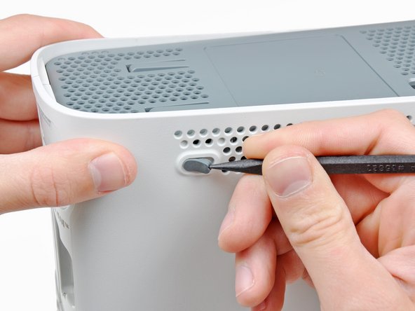
In the next few steps, you will use the tip of a spudger or the finger of an Xbox 360 opening tool to release the clips along the left and right sides of the bottom vent. Their locations are highlighted in red.
You will insert the tool into the holes molded into the white plastic side case pieces.
To release the clips, work from the front edge of the bottom vent.
While slightly lifting the front edge of the bottom vent, use the tip of a spudger to push the clips closest to the front of the bottom vent towards the inside of the console.
Stand the console vertically with the top edge facing up.
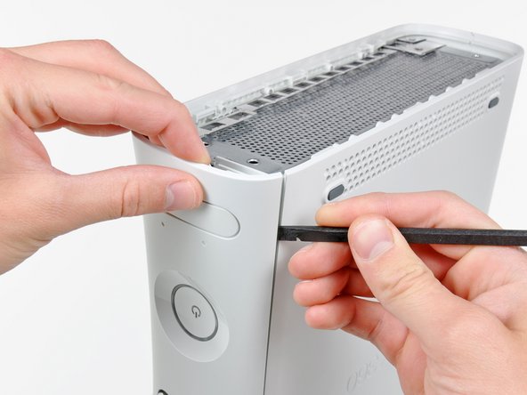
The top vent is secured to the console via clips. The first two clips are located underneath the top vent closest to the faceplate, as shown in the pictures.
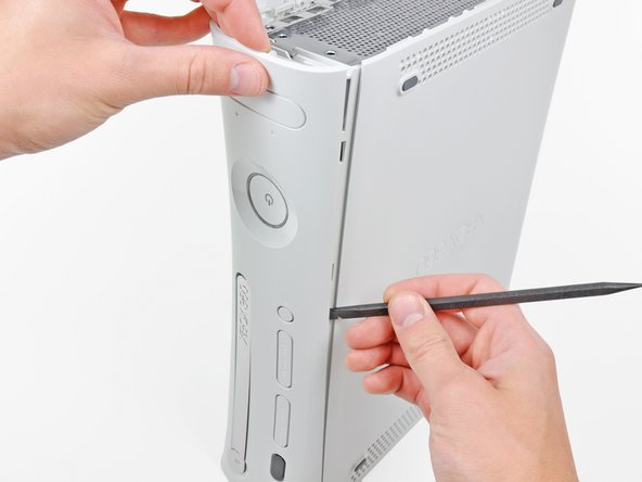
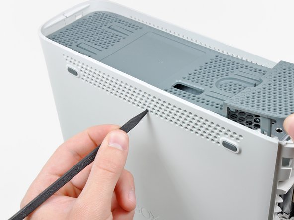
In the next few steps, you will use the tip of a spudger or the finger of an Xbox 360 opening tool to release the clips along the left and right sides of the top vent. Their locations are highlighted in red.
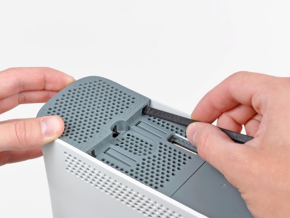
To release the clips, work from the middle of the top vent.
While slightly lifting the front edge of the top vent, use the tip of a spudger to push the clips closest to the center of the top vent towards the inside of the console.
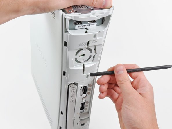
The upper and lower cases are attached via several latches, located in the front and back of the console. These latches must be disengaged to separate the upper case from the console.
Use the flat end of a spudger to release the following latches:
While pushing the upper and lower cases apart, use the tip of a spudger or the finger of an Xbox 360 opening tool to push the long clip highlighted in red toward the center of the 360.
The clip should release, leaving the clips near the power connector as the only thing holding the upper and lower cases together.
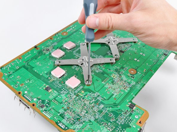
Insert your screwdriver parallel to the motherboard between the X clamp and its retaining post.
Twist the screwdriver to fully release the X clamp from its retaining post.
Repeat this process for all four corners of the X clamp.
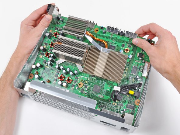
When removing the last corner of the X clamp and holding the motherboard upside down, be sure to catch the GPU heat sink to avoid damage from it falling.
To reinstall the X clamp, first start by attaching two corners to the posts on the heat sink.
While holding the third arm of the X clamp down against the post attached to the heat sink, use a small flathead screwdriver to pry the X clamp away from the heat sink post.
As you pry, press down on the arm of the X clamp until you "walk" it down into the retaining groove cut into the post attached to the heat sink.
Repeat this process for the fourth arm of the X clamp.
Insert the tip of a small flathead screwdriver between the X clamp and its retaining post on the heat sink.
Pry the X clamp away from its retaining post until it is lifted above the small groove cut into the retaining post.
If necessary, insert your screwdriver parallel to the motherboard between the X clamp and its retaining post. Twist the screwdriver to fully release the X clamp from its retaining post.
Repeat this process for all four corners of the X clamp.
When removing the last corner of the X clamp and holding the motherboard upside down, be sure to catch the CPU heat sink to avoid damage from it falling.
Remove the CPU heat sink from the motherboard. When reinstalling the CPU heat sink, be sure to apply a new layer of thermal paste.
If replacing the motherboard transfer the four thermal pads on the underside of the motherboard to your new motherboard.
Motherboard remains.
The DVD drive and the motherboard are "married" when they leave the factory. If you replace one you must replace the other. If you put any old DVD drive onto a motherboard that it is not "married" to it will only play DVDs, no games. It is possible to alter the keys so that they match.
Before heating up the motherboard, be sure to clean the old thermal paste off both the CPU and GPU until they are as clean as the processors seen in the first picture. The process for cleaning the processors can be found here.
Lay the motherboard with the processor side facing down on the flat metal bottom of the the bare chassis (with its open side facing down) as seen in the second picture. Allow the tall USB socket to hang over the edge of the chassis so the board sits flat.
Use a heat gun on the LOW setting to heat the entire back of the motherboard for one minute. Be sure to continually sweep the heat gun back and forth across the face of the motherboard to evenly heat it.
After heating the back of the motherboard for one minute, flip the motherboard over and lay it on the chassis as shown.
If you have installed the RROD fix kit already, keep the two small black heat sinks included in the kit stuck to their respective chips. The tape that is used to attach them to the chips on the board is extremely strong and attempting to remove them may damage the chips underneath. The heating process will not damage the heat sinks in any way.
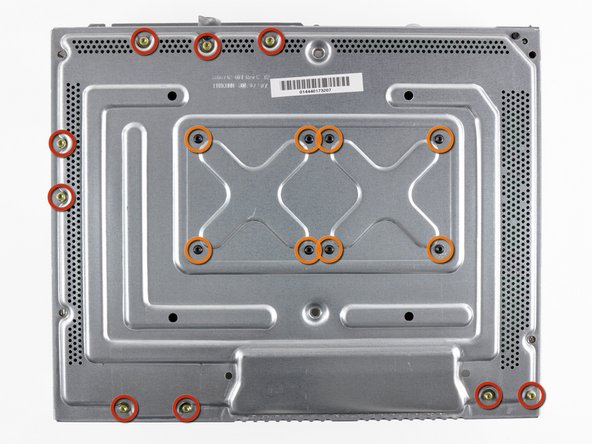
With your heat gun set to HIGH, evenly heat the area boxed in red for four minutes.
When using the heat gun on high, it is extremely important to continually move the heat gun so the stream of hot air evenly heats up the desired area.
Avoid directly heating the many cylindrical electrolytic capacitors located near the area boxed in red.
After heating the area boxed in red for four minutes, turn off your heat gun and allow the motherboard to cool down to room temperature without moving or disturbing it in any way.
At this point, we strongly recommend installing our Red Ring of Death Fix Kit to safeguard against future failure.
The heat gun they are using has a 570 F low-setting. While that doesn't give you an EXACT temperature, it should give you some idea of what they're using.