简介
Follow this guide to remove and replace the webcam cable in your Framework Laptop 12.
The webcam cable connects the front-facing camera and stereo microphones to the Mainboard. The cable threads through the left hinge and adheres to the backside of the display.
If your front-facing camera or mics stop working when you reposition your display, you may need to replace the webcam cable.
You'll encounter some component terms in this guide:
- The Input Cover is the part that contains the keyboard and trackpad.
- The Display Cover is the plastic bezel strip below the screen.
- The Top Cover is the plastic shell that houses the display.
- The Bottom Cover is the plastic shell that forms the bottom half of the laptop.
你所需要的
-
-
Before you begin repairs, unplug your laptop and shut it down from the operating system. This ensures that the laptop isn't in standby/suspend mode.
-
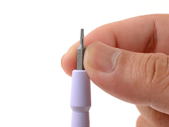
Make sure your Framework Screwdriver has the T5 Torx bit (labeled as T-5) facing outwards. If it's not, pull the bit out and flip it.
-
-
-
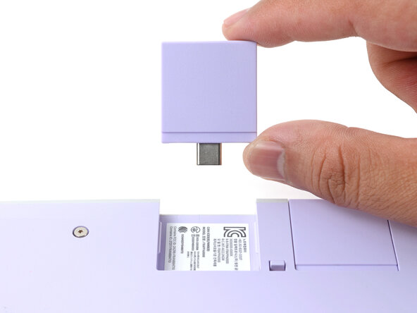
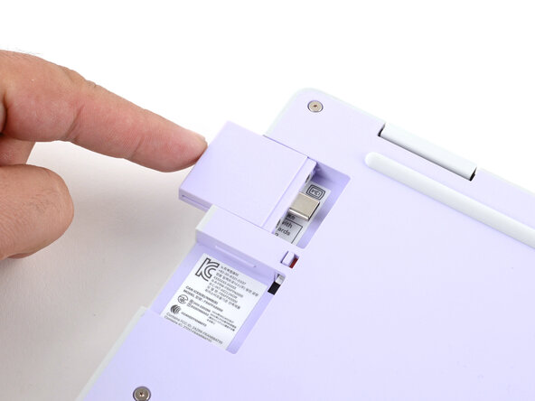
Use your fingers to flip the two Expansion Card latches (one for each side) into the unlocked position.
-
-
-
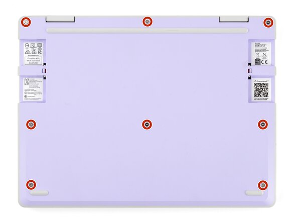
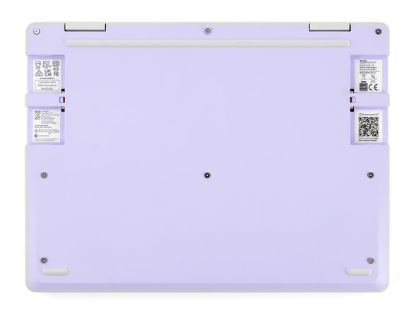
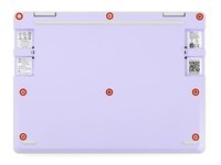
Use your Framework Screwdriver to fully loosen the eight captive T5 Torx screws on the bottom of your laptop.
-
-
-
Open the laptop lid so that both the screen and the base lie flat on your work surface.
-
-
-
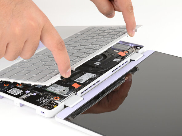
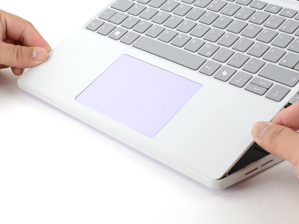
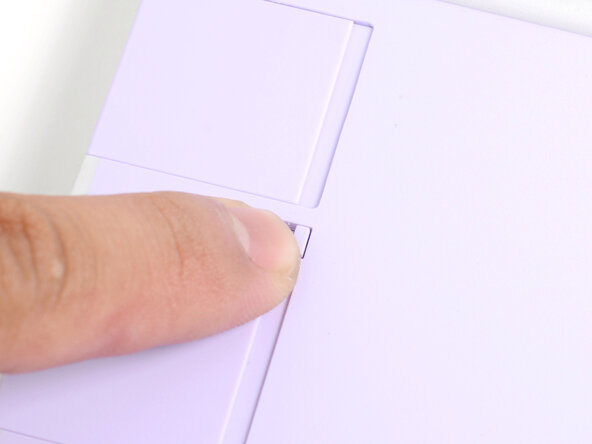
Use your fingers to grip the Input Cover in the hinge cutouts.
-
Lift upwards to swing the Input Cover up from the base of the laptop.
-
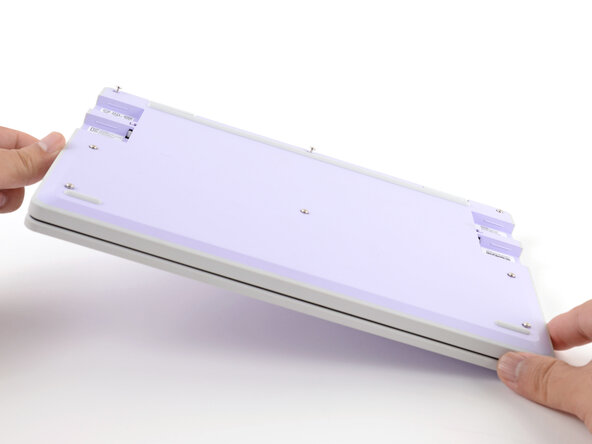
Remove the Input Cover.
-
-
-
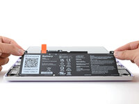
Use your Framework Screwdriver to loosen the six captive T5 Torx screws securing the battery.
-
-
-
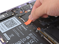
Grab the orange battery tab with your fingers and lift straight up to disconnect the battery.
-
-
-
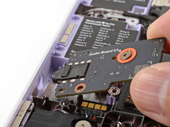
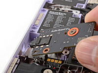
Use your Framework Screwdriver to loosen the captive T5 Torx screw securing the Audio Board along the left edge of the laptop.
-
-
-
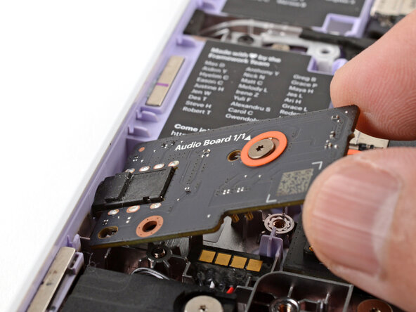
Use your fingers to lift the right edge of the Audio Board and pull it out of its recess.
-
Remove the Audio Board.
-
-
-
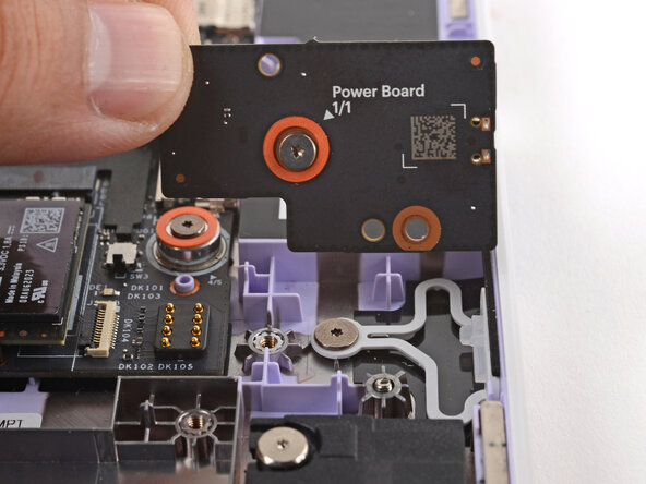
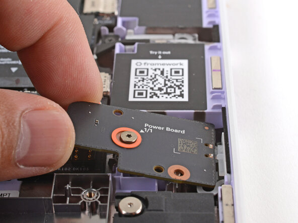
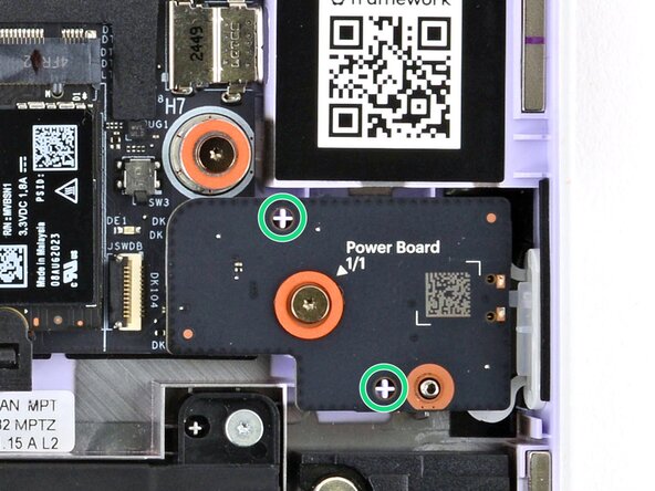
Use your Framework Screwdriver to loosen the captive T5 Torx screw securing the Power Button Board (labeled "Power Board").
-
-
-
Use your Framework Screwdriver to loosen the captive T5 Torx screw securing the Wi-Fi card bracket.
-
-
-
Grab the Wi-Fi card bracket with your fingers and slide it off the top of the Wi-Fi card.
-
Remove the bracket and store it in a safe location for reassembly.
-
-
-
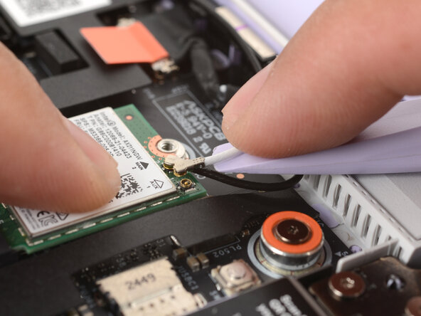
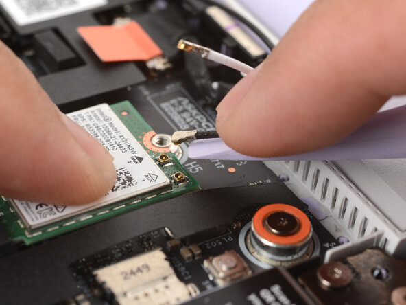
Press and hold the Wi-Fi card down with your finger.
-
Slide the flat edge of your Framework Screwdriver under the white antenna cable, as close to the metal head as possible.
-
Gently lift the connector straight up to disconnect the white antenna cable.
-
Repeat the procedure with the black antenna cable.
-
-
-
Grab the Wi-Fi card by the edges and pull it out of its socket.
-
Remove the Wi-Fi card.
-
-
-
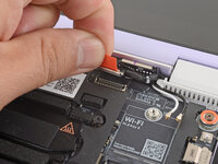
Use your fingers to grab the orange tab on the webcam cable, located near the left hinge.
-
Lift straight up to disconnect the cable.
-
-
-
Use your fingers to grab the orange tab on the display cable, located near the right hinge.
-
Lift straight up to disconnect the cable.
-
-
-
Use your Framework Screwdriver to loosen the five captive T5 Torx screws securing the Mainboard.
-
-
-
Use your fingers to grab the Mainboard by its edges.
-
Lift and remove the Mainboard.
-
-
-
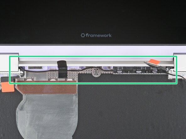
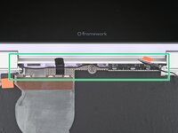
Use your fingers to lift the black plastic loop securing the antenna cable, near the heat vents by the left hinge.
-
-
-
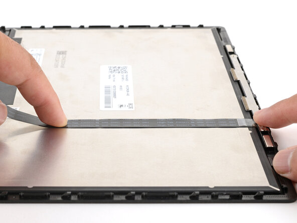
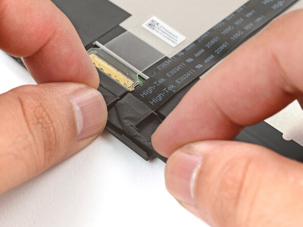
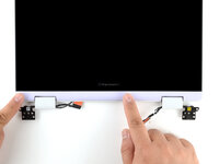
Use your fingers to gently lift the webcam cable out of its plastic channel.
-
-
-
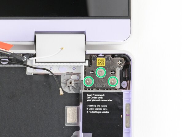
Use your Framework Screwdriver to remove the six (three per hinge) 4.5 mm‑long T5 Torx screws securing the two hinges.
-
-
-
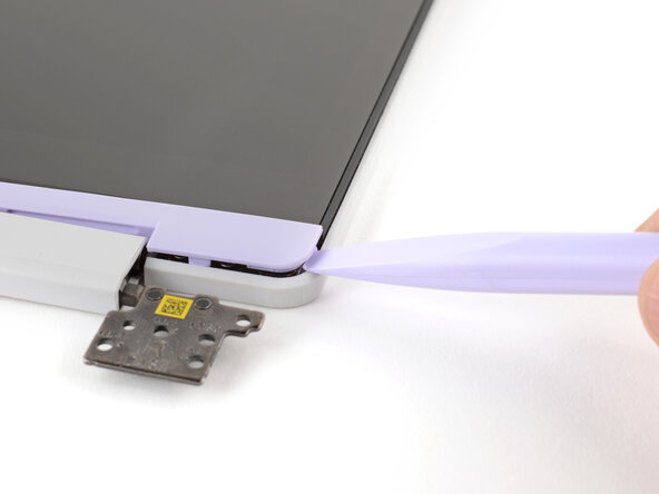
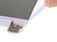
Use the flat end of your Framework Screwdriver to pry up the right edge of the Display Cover.
-
-
-
-
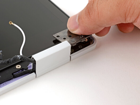
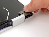
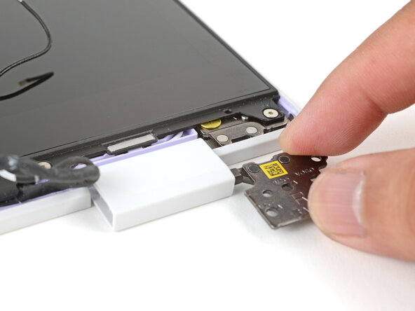
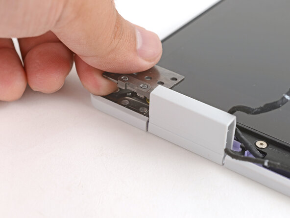
Use your fingers to twist the right hinge plate until it's flipped on top of the display.
-
-
-
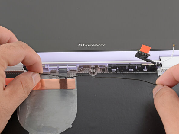
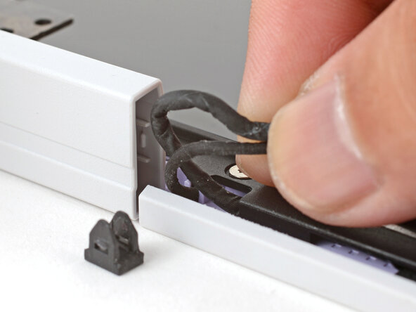
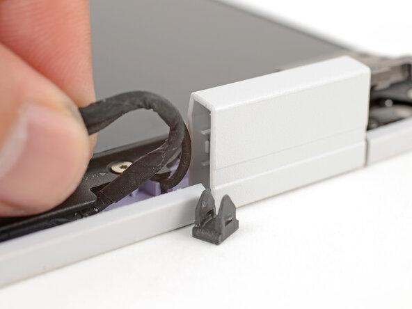
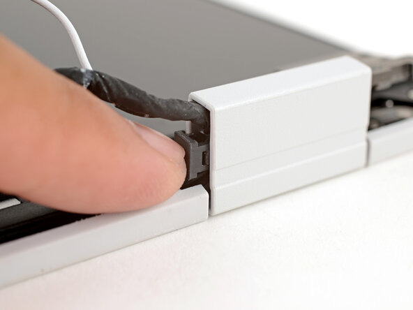
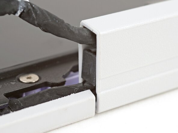
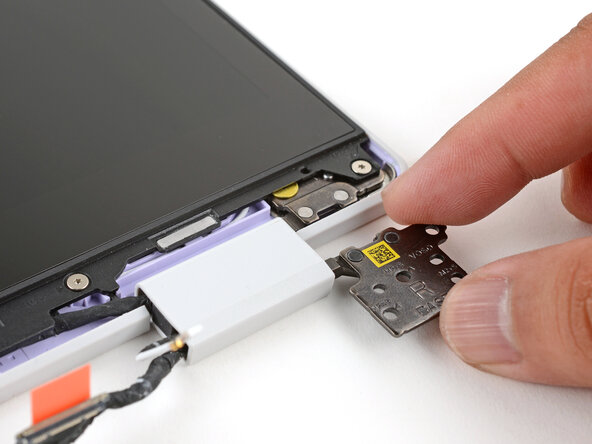
Use your fingers to grab the two cables coming out of the left hinge.
-
Pull gently to pop out the black cable clip and release the cables.
-
Store the cable clip for reassembly.
-
-
-
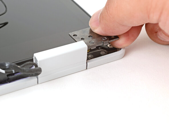
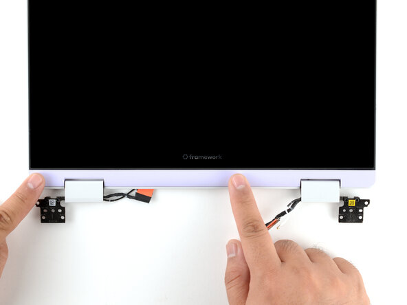
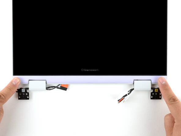
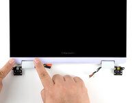
Use your fingers to twist both hinge plates back down so they lay flat on your work surface.
-
-
-
Use your Framework Screwdriver to remove the four 3.3 mm‑long T5 Torx screws securing the display to the Top Cover.
-
-
-
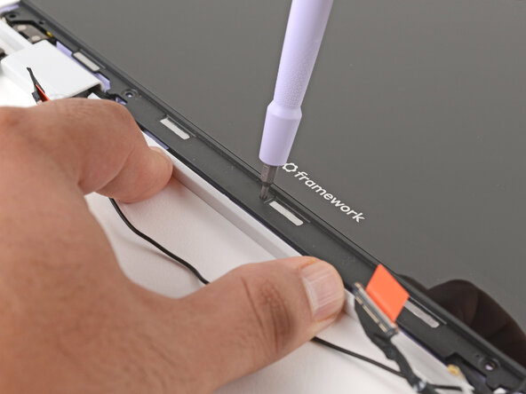
Use your fingers to hold the bottom edge of the Top Cover in place.
-
Insert the bit end of your Framework Screwdriver into the small hole on the display, below the Framework logo.
-
Slide the display down towards the hinge edge to release the tabs holding the top edge of the display in place.
-
-
-
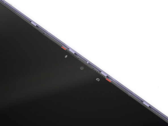
Use your Framework Screwdriver to remove the two 3.3 mm‑long T5 Torx screws securing the webcam bracket on the top edge of the display.
-
-
-
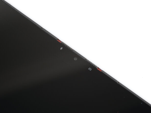
Use the flat end of your Framework Screwdriver to lift the webcam out of its recess.
-
Flip the webcam over and gently hold it down with your fingers.
-
-
-
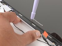
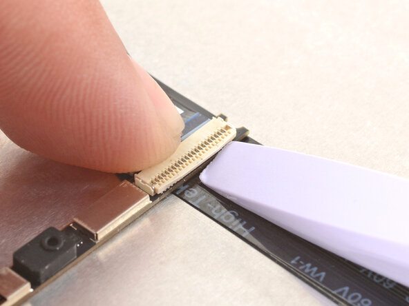
Use the flat end of your Framework Screwdriver or a fingernail to gently pry up the locking tab on the webcam cable ZIF connector.
-
-
-
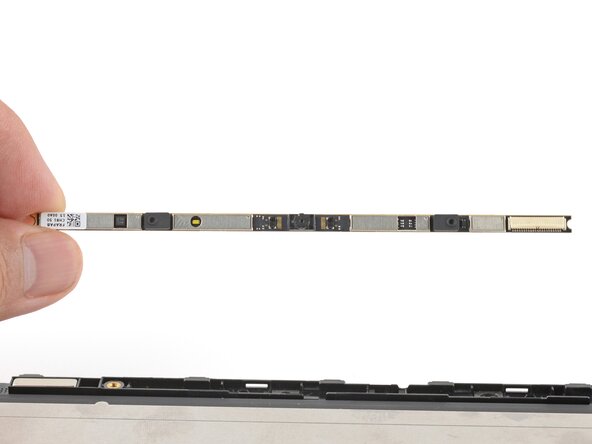
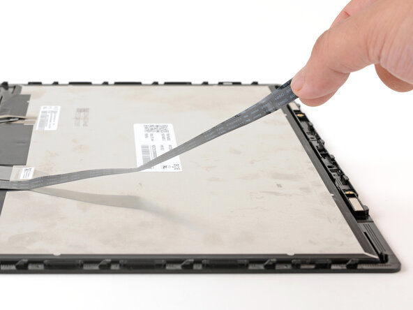
Grab the webcam cable with your fingers and slowly peel it away from the display.
-
Carefully move the cable off of the display.
-
-
-
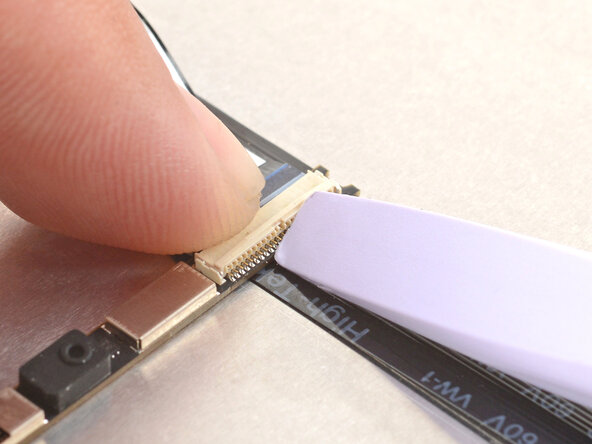
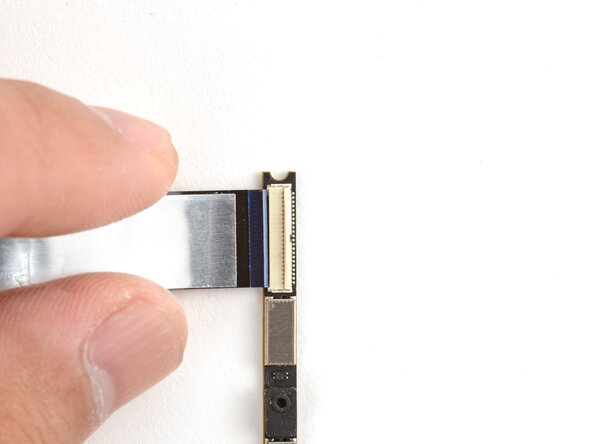
Hold the webcam cable with the shiny side facing up.
-
Slide the cable into the webcam module's ZIF connector, up to the printed line on the cable.
-
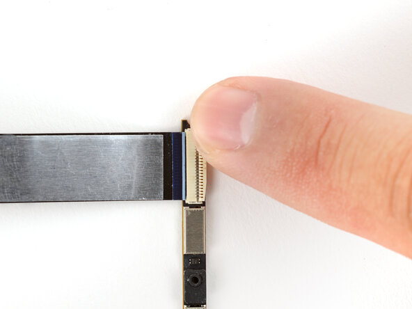
Use your finger to flip down and gently press the locking tab in place.
-
-
-
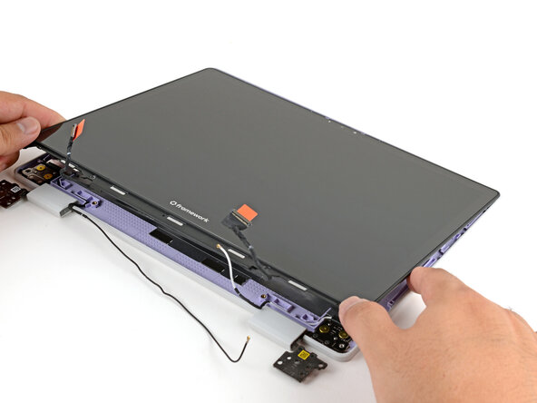
Lay the display in place in the Top Cover, such that the top edge of the display is slightly below the top edge of the Top Cover.
-
-
-
Use your Framework Screwdriver to install the four 3.3 mm‑long T5 Torx screws to secure the display to the Top Cover.
-
-
-
Use your fingers to lift the Top Cover hinges over the Bottom Cover lip.
-
Lay the hinges in place in the Bottom Cover.
-
-
-
Carefully lay the Mainboard in the laptop.
-
Use the two alignment pins to help align the Mainboard to the laptop.
-
Be careful not to trap the webcam, display, and antenna cables under the Mainboard as you set it in place.
-
-
-
Align the Wi-Fi card's gold contacts and notch with the socket on the Mainboard.
-
Insert the Wi-Fi card into the socket at a shallow angle. The gold contacts should mostly be covered by the socket.
-
-
-
Hold the Wi-Fi card down with your finger.
-
Position the black antenna cable connector over the left Wi-Fi card's coaxial socket.
-
Use your finger to press the connector into place. You should feel a faint click, and the cable will stay attached to the socket by itself.
-
Repeat the procedure with the white antenna cable.
-
-
-
Use your fingers to lay the Power Button Board in place.
-
Use the two plastic pins on the laptop to align the Power Button Board.
-
-
-
Insert the Audio Board into the laptop at an angle to help align the headphone jack.
-
Use the two plastic alignment pins on the laptop to help with final alignment.
-
-
-
Angle the bottom edge of the Input Cover towards the base of the laptop.
-
Align and insert the bottom edge of the Input Cover into the base of the laptop.
-
Lower the Input Cover's top edge onto the laptop until the magnets snap it in place.
-
-
-
Use your Framework Screwdriver to tighten the eight captive T5 Torx screws on the bottom of your laptop.
-


You finished fixing your Framework Laptop!
Take your e-waste to an R2 or e-Stewards certified recycler.
If you need help, contact Framework support.

团队
