跳转到主内容

2.3GHz, 2.6GHz, or 2.7GHz quad-core Intel Core i7 processor (Turbo Boost up to 3.7GHz) with 6MB shared L3 cache.

561 个问题 查看全部

The connector for the lvds cable on logic board missaligned

Hi All,

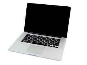
Recently, I replaced the speaker for my macbook pro. During the assembly, I could not match the display cable with its connector in logic board.

It seems I forced it too hard so that it is a little bit damage. It seems that both cable and its logic board are quite fragile.

I bought new cable, but still, it cannot match the socket connector.

I come to a conclusion that both the cable and the socket connector on logic board are damaged.

My question, other than replacing logic board, is it possible just to fix the socket connector?

Thanks in advance,

Putu
回答此问题 我也有这个问题

这是一个好问题吗?

得分 0
添加一条评论

3个答案

Hi Putu,

I have not seen the connector you describe but can offer some advice.

Apple logic board connectors are delicate, complex and vary in design. They are installed jointly with many other components in production using flow soldering techniques, and are very difficult to change individually - you may not even be able to obtain the one you need.

Best option is for you to take a powerful magnifier and examine the connector on the board alongside the new cable to understand how they mate together.

It may be some part of the housing, or connecting pins, have become bent or misaligned. You might be able to correct any damage by careful levering using a fine pointed tool, then keep gently retrying to install the cable until it looks to be seated correctly.

Persevere with this and try not to force the parts to come together if there is excessive resistance.

Hope this works for you..good luck!

这个答案有帮助吗?

得分 0

4条评论:

Thanks a lot Ray Jones, for very comprehensive answer. That makes sense. I can consider that. To use a magnifier to better understand what is actually happening. At least I can learn for future. :).

完成的

No problem. Dan's answer below is an excellent one, and shows if the connector cannot be adjusted to accept the cable, a replacement is inexpensive. However heed his warning well...getting the old part off will definitely require the wide soldering bit he describes to melt all joints to the board simultaneously. Installing the new connector may not be straightforward with the same tool, possibly requiring individual soldering to each pin using a very small diameter iron tip.

完成的

@rayjones10075 - Sorry, I didn’t get into how to solder the new connector down. You need to fully clean the old solder off the pads using solder-wick and then re-tin the pads. The connector also needs to have its pins tinned as well. There are a few ways to solder down the connector. My approach is to align the connector and tack it down by the connectors frame at the ends, then I use solder paste wiping it across the pins, then using a narrow tip hot air system with shields around the area so only the pin area is exposed I heat the pins. The paste magically clings to the pins and the tinned pad spaces.

You can also use a small iron and using liquid flux to help wetting the area thus the regular solder will follow the pins in a wiping action with the iron running across the pins. You may need to touch up a bridged set of pins or two and you should clean with iso and using a dental pick make sure the gaps don’t have any solder balls which could short across.

完成的

Dan, thanks for this further comment with detailed guidance which will be invaluable to many here. Certainly has me better informed! Going to tuck this knowledge away for the day I need to attempt such a repair :)

完成的

添加一条评论

Hi @merta63333 Yes! The logic boards display connector can be replaced. I’ll warn you the solder pads can be lifted if not done properly with the correct soldering iron. What is needed is a fairly high wattage iron with a special tip for the task often called a Flat Blade Iron Tip which fits the given iron.

Basically, you need to heat all of the pins at once and keep the solder liquid until you have slid the connector away otherwise you run the risk of damaging the thin solder pads underneath.

I would recommend finding someone with deeper experience on reworking logic boards with the needed iron.

Here’s the needed connector LCD Display LVDS/eDP Connector

这个答案有帮助吗?

得分 0

1条评论:

Hi Dan, thanks for taking time to share some insights and quite precise steps. I really appreciate that. I may consider your advice to look for someone with more experience to handle that. :)

完成的

添加一条评论

@merta63333 let's see the damage to both, the male and female connector. Post some good images with your question. 在已经存在的问题里加入图片

If you have never soldered on a logic board, this may not be the easiest connector to work on. For a definite workable procedure, check this video I found that the most successful way of doing it for me, is by a process called drag soldering. I prefer to stay away from straight, chisel type tips and hot air, since that can affect the other components around that connector. I use use a Hakko T18-BR02 which has worked well for many of my replacements.

To replace your cable, use this guide MacBook Pro 15" Retina Display Mid 2012 LCD Kabel Replacement

Ultimately, the best way of repairing this, is by doing it the way you are comfortable with. Telling you what tools, technique or consumables I use, does not help you much. Everybody has to develop their own technique of getting it accomplished.

There are many of great people on here, that are capable of doing this repair for you. Remember, it is all up to you, your skills, your tools and your comfort level.

iFixit图片

指南

在已经存在的问题里加入图片

难度:

非常容易

2 - 5 minutes

MacBook Pro 15" Retina Display Mid 2012 LCD cable图片

指南

MacBook Pro 15" Retina Display Mid 2012 LCD Cable Replacement

难度:

中等

30 minutes - 2 hours

这个答案有帮助吗?

得分 0
添加一条评论

添加你的答案

merta 将永远感激不已
浏览统计数据:

过去 24 小时: 0

过去 7 天: 0

过去 30 天: 6

总计 86