No internal lcd video output
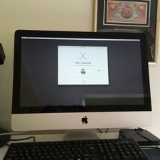
Got this Mac about a year ago & been trying to diagnose it, it was originally supposed to be an LVDS issue but I replaced that still the same fault, no video output on the internal screen, it runs perfect with an external screen so I then replaced the following parts to no avail:
Backlight inverter
Lcd (LM215WF3 SDA1)
Video card (4670)
diagnostic LED#1,2,3 come on but 4 does not, all cables are fine so I'm now getting to the point where it's now starting to cost more money, I have probed the test points & get nothing on pin13 for the backlight signal so I'm guessing something has blown on the logic board but don't see anything obvious, is there anything else I can check, obviously I could replace the logic board but it seems a shame seeing as it runs with an external screen without problems
Many thanks


10条评论
Just to recap, you replaced the LCD, the backlight board as well as the video card. What do you mean by this "supposed to be an LVDS issue but I replaced that"?
由 oldturkey03 完成的
Hi old Turkey, I mean the fault paperwork attached to the machine (came from a joblot) said "needs display cable" so I replaced that, I have a good working knowledge of Apple products & am familiar with having to replace exact part numbers, started with the cheapest part & worked my way up but I've hit a blank now so I'm guessing I need to go component level repair on it
Regards
由 Brian 完成的
Brian, this is still a comment and want to make sure if you checked the test points on your board. Pin 13 is of interest.
"Logic Board Test Points
Test points, which can be used to verify proper power flow, are accessible in center of logic board, to right of SMC Reset button, when LCD panel is removed. All voltages given in Troubleshooting Symptom Charts assume that computer is plugged into a known-good power outlet with a known-good AC cable. Some guidelines for using test points:
• Warning: HIGH VOLTAGE: Use extreme caution when live testing!
• Do NOT lean over or touch the power supply area during live testing.
• Keep your fingers behind finger guards on test probes when measuring.
• Turn dial of voltmeter/multimeter to measure DC (direct current, usually indicated by a solid horizontal line over dashes). If your voltmeter requires a set voltage range, choose a DC range that includes the voltage you are measuring.
• Connect black probe to ground. Connect red probe to test point and verify voltage.
[image|464841|align=left]
由 oldturkey03 完成的
Yes, been through the deep dive in the service manual, I'll have another look later today as I'm sure there are other pins not giving a reading also, I forget which ones sorry, would it be possible there's a fault in the PSU not putting power out to drive the backlight board? I haven't as yet tried another PSU
Regards
由 Brian 完成的
Yes it is possible.
由 oldturkey03 完成的
显示更多的5条评论