跳转到主内容

iMac G5 17" Model A1058 Logic Board Replacement

你所需要的

  1. iMac G5 17" Model A1058 Logic Board Replacement, Rear Panel: 步骤 1 中的图像 1,1
    • Lay the iMac display-side down on a flat surface.

    • Loosen the three Phillips screws securing the rear panel to the iMac.

    • These screws are captive in the iMac. The center screw will stop turning after about 3.5 turns and the outer screws will stop turning after about 5.5 turns. Do not try to remove these screws from your iMac.

  2. iMac G5 17" Model A1058 Logic Board Replacement: 步骤 2 中的图像 1,3 iMac G5 17" Model A1058 Logic Board Replacement: 步骤 2 中的图像 2,3 iMac G5 17" Model A1058 Logic Board Replacement: 步骤 2 中的图像 3,3
    • Lift the rear panel slightly from the bottom edge of the iMac.

    • Pull the rear panel toward yourself and remove it from the iMac.

  3. iMac G5 17" Model A1058 Logic Board Replacement, RAM: 步骤 3 中的图像 1,3 iMac G5 17" Model A1058 Logic Board Replacement, RAM: 步骤 3 中的图像 2,3 iMac G5 17" Model A1058 Logic Board Replacement, RAM: 步骤 3 中的图像 3,3
    • Rotate each of the two RAM retaining arms away from the RAM chip.

    • Pull the RAM chip straight away from its socket.

    • Repeat this process for the other RAM chip.

    • Be sure the RAM arms are fully rotated away from the RAM socket before reinstalling any RAM chips.

  4. iMac G5 17" Model A1058 Logic Board Replacement, Optical Drive: 步骤 4 中的图像 1,1
    • Remove the three 8 mm brass Phillips screws securing the optical drive to the midplane.

  5. iMac G5 17" Model A1058 Logic Board Replacement: 步骤 5 中的图像 1,3 iMac G5 17" Model A1058 Logic Board Replacement: 步骤 5 中的图像 2,3 iMac G5 17" Model A1058 Logic Board Replacement: 步骤 5 中的图像 3,3
    • Lift the optical drive near the connector to separate it from the logic board.

    • Lift the free end of the optical drive just enough to clear the fan cover. Lifting the free end of the optical drive too far may break the plastic positioning pins off the front bezel.

    • Lift the free end of the optical drive slightly, then pull it away from the edge of the rear case to clear the two plastic positioning pins.

    • Lift the optical drive out of your iMac.

    • When reinstalling your optical drive it may be necessary to set the bezel attached to the open end of the drive on the plastic positioning pins molded into the front bezel of the iMac and pull the connector side of the drive toward the edge of the rear case, bending it outward slightly, to properly seat the connector.

  6. iMac G5 17" Model A1058 Logic Board Replacement, Power Supply: 步骤 6 中的图像 1,2 iMac G5 17" Model A1058 Logic Board Replacement, Power Supply: 步骤 6 中的图像 2,2
    • Rotate the center Phillips screw on the bottom of the iMac clockwise until the rear panel clamp contacts the edge of the case.

    • On our specific machine, the threaded portion of the clamp broke off the clamp body causing the center screw to turn without moving the bracket. If your machine is broken like ours, skip to the next step.

  7. iMac G5 17" Model A1058 Logic Board Replacement: 步骤 7 中的图像 1,3 iMac G5 17" Model A1058 Logic Board Replacement: 步骤 7 中的图像 2,3 iMac G5 17" Model A1058 Logic Board Replacement: 步骤 7 中的图像 3,3
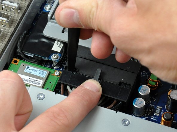
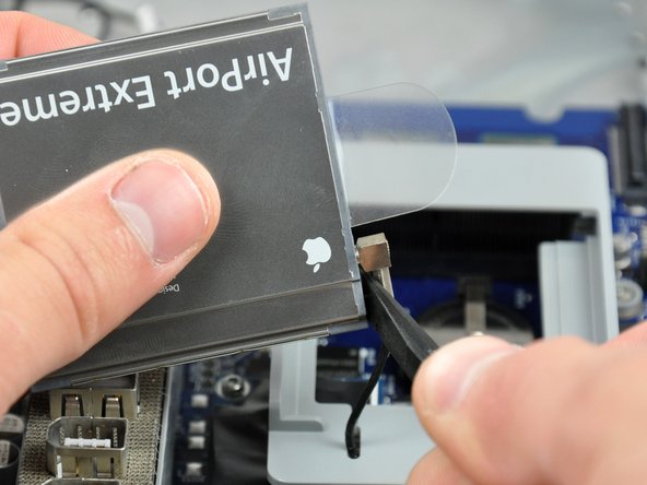
    • While depressing the connector lock, insert the flat end of a heavy duty spudger into the gap between the power supply connector and its socket.

    • Twist the heavy duty spudger to slightly separate the connector from its socket.

    • It will be necessary to work from alternate sides until the connector is free.

    • Your power supply may have an ambient light sensor cable attached from the power supply to the logic board. If so, carefully use a spudger to push out the cable towards you using the sides of the cable alternatively to help you slide it out.

  8. iMac G5 17" Model A1058 Logic Board Replacement: 步骤 8 中的图像 1,1
    • Pull the power supply connector straight away from its socket on the logic board.

    • This step is very simple if you remove the power supply first.

  9. iMac G5 17" Model A1058 Logic Board Replacement: 步骤 9 中的图像 1,1
    • Remove the three Phillips screws securing the power supply to the chassis.

    • All three screws are captive in the power supply.

    • To aid in removal, it may be helpful to lift the center screw slightly away from the midplane.

  10. iMac G5 17" Model A1058 Logic Board Replacement: 步骤 10 中的图像 1,2 iMac G5 17" Model A1058 Logic Board Replacement: 步骤 10 中的图像 2,2
    • There are several capacitors mounted to the logic board in close proximity to the power supply. Try not to disturb them, as they are delicate and may break off the board.

    • Grab the power supply from each side and rotate its top edge toward yourself until it clears the logic board.

    • Lift the power supply out of the midplane.

    • The power supply requires a large amount of force to remove. You may need to slightly bend the edge of the front case toward yourself for enough clearance to remove the power supply.

  11. iMac G5 17" Model A1058 Logic Board Replacement, Logic Board: 步骤 11 中的图像 1,1
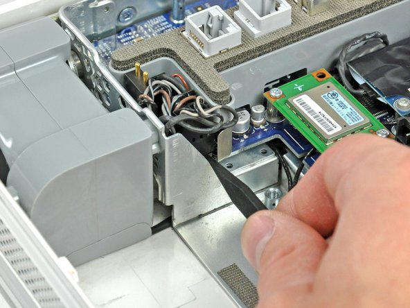
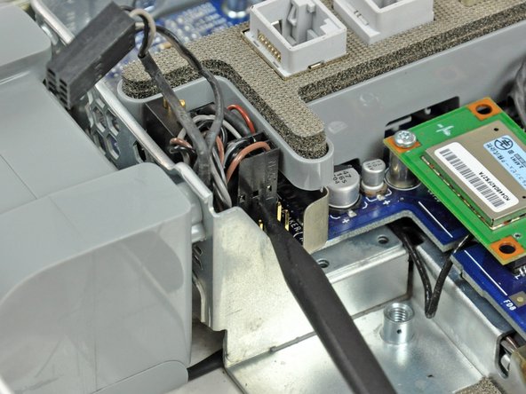
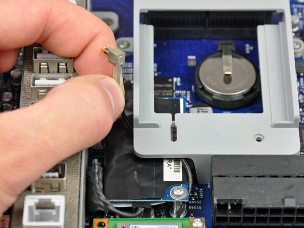
    • Disconnect the hard drive thermal sensor cable from the hard drive thermal sensor board.

    • During reassembly, use the tip of your spudger to plug the hard drive thermal sensor back into the socket on the hard drive thermal sensor board.

  12. iMac G5 17" Model A1058 Logic Board Replacement: 步骤 12 中的图像 1,2 iMac G5 17" Model A1058 Logic Board Replacement: 步骤 12 中的图像 2,2
    • Remove the two 13 mm T10 Torx screws securing the fan duct to the midplane.

    • Lift the fan duct out of the midplane.

  13. iMac G5 17" Model A1058 Logic Board Replacement: 步骤 13 中的图像 1,2 iMac G5 17" Model A1058 Logic Board Replacement: 步骤 13 中的图像 2,2
    • Remove the two Phillips screws securing the fan cover to the midplane.

    • The shouldered Phillips screw belongs in the lower left corner of the fan cover.

    • Lift the fan cover out of the midplane.

  14. iMac G5 17" Model A1058 Logic Board Replacement: 步骤 14 中的图像 1,2 iMac G5 17" Model A1058 Logic Board Replacement: 步骤 14 中的图像 2,2
    • Remove the two 7 mm shouldered Phillips screws securing the display data cable to the logic board.

    • Using its black pull tab, pull the display data cable connector straight up off its socket on the logic board.

  15. iMac G5 17" Model A1058 Logic Board Replacement: 步骤 15 中的图像 1,1
    • Disconnect the SATA power cable by depressing the lock mechanism and pulling the connector straight away from its socket.

    • Pull the connector parallel to the face of the logic board.

  16. iMac G5 17" Model A1058 Logic Board Replacement: 步骤 16 中的图像 1,1
    • Disconnect the SATA data cable by pulling its connector straight up off the logic board.

  17. iMac G5 17" Model A1058 Logic Board Replacement: 步骤 17 中的图像 1,2 iMac G5 17" Model A1058 Logic Board Replacement: 步骤 17 中的图像 2,2
    • Disconnect both fans by pulling their connectors straight up off the logic board.

    • The larger of the two fans connects closest to the top edge of the logic board.

    • On the ALS model, the larger fan connector is attached with a clip. Depress the clip while carefully removing the plug.

  18. iMac G5 17" Model A1058 Logic Board Replacement: 步骤 18 中的图像 1,1
    • Slide the inverter-to-display cable connector from under the metal clip on the midplane.

  19. iMac G5 17" Model A1058 Logic Board Replacement: 步骤 19 中的图像 1,1
    • Disconnect the inverter-to-display cable connector by pulling it straight away from its socket.

  20. iMac G5 17" Model A1058 Logic Board Replacement: 步骤 20 中的图像 1,2 iMac G5 17" Model A1058 Logic Board Replacement: 步骤 20 中的图像 2,2
    • Remove the single 8 mm brass Phillips screw securing the inverter to the logic board.

    • Lift the inverter straight up off the pins on the logic board.

    • Be sure to lift the inverter straight up off the logic board, as the connector pins are very long and easily bent. If the pins bend during removal, use the connector on the inverter as a guide to bend them straight.

  21. iMac G5 17" Model A1058 Logic Board Replacement: 步骤 21 中的图像 1,1
    • Disconnect the inverter cable from the logic board by pulling it straight up from its socket.

  22. iMac G5 17" Model A1058 Logic Board Replacement: 步骤 22 中的图像 1,1
    • De-route the inverter cable connector from the channel in the logic board.

    • Lift the inverter out of the midplane and set it aside.

    • Skip this step if yours is an ALS model; this part is not present.

  23. iMac G5 17" Model A1058 Logic Board Replacement: 步骤 23 中的图像 1,1
    • The connectors removed in the next few steps slide onto long pins attached to the logic board. Be sure to only pull them straight up from the logic board to avoid bending the pins.

    • If you do bend the pins during removal, use the connectors as a guide to bend them back straight.

    • Use the tip of a spudger to lift the speaker cable connector from its lower edge straight up off the logic board.

  24. iMac G5 17" Model A1058 Logic Board Replacement: 步骤 24 中的图像 1,2 iMac G5 17" Model A1058 Logic Board Replacement: 步骤 24 中的图像 2,2
    • Insert the tip of a spudger into the center hole punched into the side of the lower fan connector.

    • With the spudger still inserted, lift the lower fan connector straight up off the logic board.

    • The speaker cable connector attaches to the pins closest to the power supply. It is the only connector with four wires. The microphone cable attaches to the pins furthest away from the power supply and is the only connector with a dark orange wire.

  25. iMac G5 17" Model A1058 Logic Board Replacement: 步骤 25 中的图像 1,1
    • Use the tip of a spudger to lift the microphone cables enough to grab the microphone cable connector and pull it straight up off the logic board.

  26. iMac G5 17" Model A1058 Logic Board Replacement: 步骤 26 中的图像 1,1
    • Using its attached pull tab, lift the AirPort card slightly and pull it straight away from its socket.

    • This step does not apply to the ALS model; this bracket is not present. The card attaches with a pair of T6 Torx screws and looks slightly different from this picture.

  27. iMac G5 17" Model A1058 Logic Board Replacement: 步骤 27 中的图像 1,1
    • Insert the flat end of a spudger between the antenna connector and the body of the AirPort card.

    • Push the spudger away from the AirPort card to disconnect the AirPort antenna.

    • When reassembling your iMac, be sure to insert the AirPort card the way it was before disassembly.

    • This step does not apply to the ALS model.

  28. iMac G5 17" Model A1058 Logic Board Replacement: 步骤 28 中的图像 1,2 iMac G5 17" Model A1058 Logic Board Replacement: 步骤 28 中的图像 2,2
    • Use a spudger to push the AirPort antenna cable through the slot in the AirPort card bracket.

    • De-route the AirPort antenna out from under the AirPort bracket.

    • This step does not apply to the ALS model.

  29. iMac G5 17" Model A1058 Logic Board Replacement: 步骤 29 中的图像 1,1
    • Remove the two T6 Torx screws securing the Bluetooth board to the logic board.

    • Some models may not have a blue tooth module.

  30. iMac G5 17" Model A1058 Logic Board Replacement: 步骤 30 中的图像 1,2 iMac G5 17" Model A1058 Logic Board Replacement: 步骤 30 中的图像 2,2
    • Depending on your iMac model, the bluetooth board may be blue. Use your fingertip to lift the Bluetooth board from its right edge, disconnecting it from its socket on the logic board.

    • Be sure to lift the Bluetooth board from its right edge only. Trying to lift it up from any other side will shear the connector off the Bluetooth board.

    • Use the flat end of a spudger to pry the Bluetooth antenna connector up off the Bluetooth board.

  31. iMac G5 17" Model A1058 Logic Board Replacement: 步骤 31 中的图像 1,1
    • Remove the following nine screws securing the logic board to the midplane:

    • Six 7 mm T10 Torx.

    • Three long 20 mm brass coarse-thread Phillips.

  32. iMac G5 17" Model A1058 Logic Board Replacement: 步骤 32 中的图像 1,2 iMac G5 17" Model A1058 Logic Board Replacement: 步骤 32 中的图像 2,2
    • Lift the logic board from its left edge to clear the two positioning pins connected to the midplane.

  33. iMac G5 17" Model A1058 Logic Board Replacement: 步骤 33 中的图像 1,2 iMac G5 17" Model A1058 Logic Board Replacement: 步骤 33 中的图像 2,2
    • Grab the logic board from both edges and lift it out of the midplane, minding any cables that may get caught.

    • When reinstalling your logic board, be sure to clean and apply a new layer of thermal paste to the U3 chip (highlighted in red) located on the underside of your logic board as well as its copper heat sink attached to the midplane.

    • We have a thermal paste guide that makes applying thermal paste a snap.

结论

To reassemble your device, follow these instructions in reverse order.

61等其他人完成本指南。

0条评论

添加评论

浏览统计数据:

过去 24 小时: 2

过去 7 天: 15

过去 30 天: 43

总计 80,637