跳转到主内容

当前版本的文档还未经巡查,您可以查看最新的已查核版本

你所需要的

  1. 这个步骤还没有翻译 帮忙翻译一下

    : 步骤 1 中的图像 1,1
    • Remove the sticker on the underside of the device.

    • Remove the four 3.1x23.5 mm T10 screws underneath the sticker.

    • While you're at it, remove the four 3.1x7.5 mm T10 screws beneath the sticker. Make note of the sizes and locations of the screws.

  2. 这个步骤还没有翻译 帮忙翻译一下

    : 步骤 2 中的图像 1,3 : 步骤 2 中的图像 2,3 : 步骤 2 中的图像 3,3
    • Remove the back panel.

    • Remove the black panels on either side of the Kinect, and remove the 3.1x7.5mm T10 screws underneath them.

  3. 这个步骤还没有翻译 帮忙翻译一下

    : 步骤 3 中的图像 1,3 : 步骤 3 中的图像 2,3 : 步骤 3 中的图像 3,3
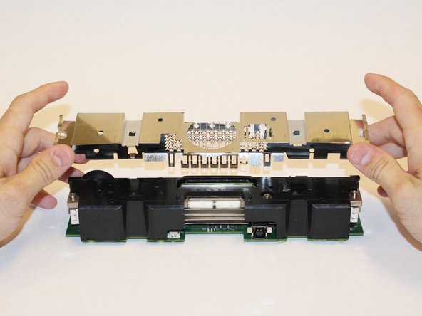
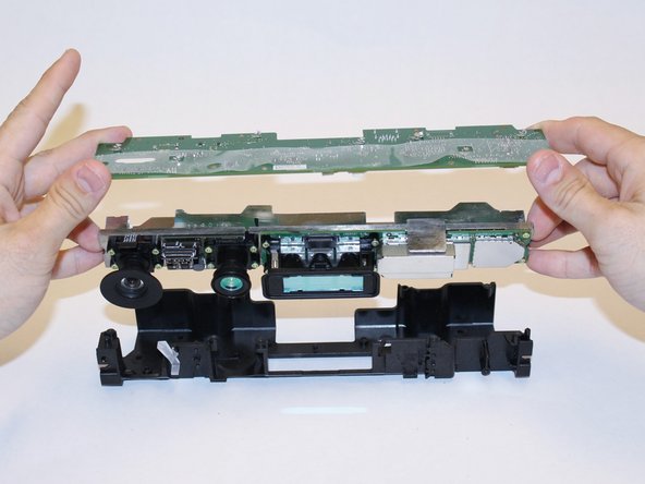
    • Using your thumbs, press firmly against the outer case on either side of the stand. This will disengage the internal assembly.

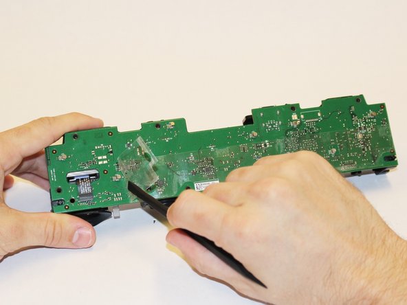
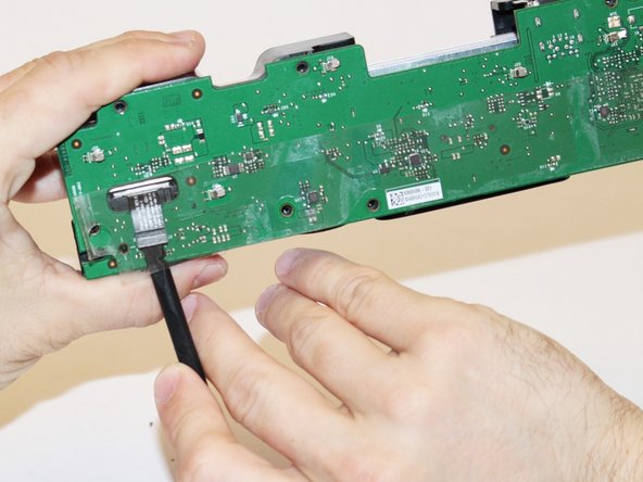
    • Lift the internal assembly with the spudger.

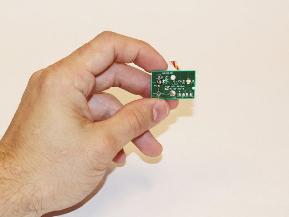
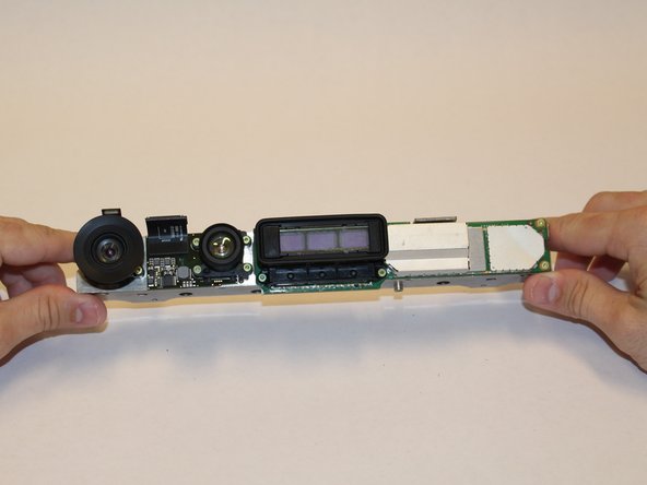
    • Remove the assembly from the case. You now have access to the inner shell of the kinect, along with the heat sink, microphone, and LED sensor.

  4. 这个步骤还没有翻译 帮忙翻译一下

    : 步骤 4 中的图像 1,2 : 步骤 4 中的图像 2,2
    • Remove the eight 2.9x7.6 mm T9 screws from the rear of the internal case.

    • Lift the internal metal case from the plastic shell enclosing the heat sink assembly.

  5. 这个步骤还没有翻译 帮忙翻译一下

    : 步骤 5 中的图像 1,3 : 步骤 5 中的图像 2,3 : 步骤 5 中的图像 3,3
    • Disconnect the ribbon cable between the sensor driver board and the motherboard.

    • Remove the 3.0x7.5 mm T9 screw holding the sensor driver board to the heat sink.

    • Remove the infrared sensor board for the Kinect.

  6. 这个步骤还没有翻译 帮忙翻译一下

    : 步骤 6 中的图像 1,3 : 步骤 6 中的图像 2,3 : 步骤 6 中的图像 3,3
    • Detach the ribbon cable leading to the microphone with the tweezers.

    • Remove the four 3.1x7.7 mm T9 screws connecting the microphone to the heat sink assembly.

    • Remove the stand.

  7. 这个步骤还没有翻译 帮忙翻译一下

    : 步骤 7 中的图像 1,3 : 步骤 7 中的图像 2,3 : 步骤 7 中的图像 3,3
    • Remove the eight 3.0x7.6 mm T9 screws from the motherboard.

    • Peel away the plastic film from the motherboard using the spudger.

    • Detach the ribbon cable leading to the color camera using the spudger.

  8. 这个步骤还没有翻译 帮忙翻译一下

    : 步骤 8 中的图像 1,3 : 步骤 8 中的图像 2,3 : 步骤 8 中的图像 3,3
    • Lift the motherboard and the heat sink assembly from the plastic shell. The components attached to the heat sink are now accessible.

  9. 这个步骤还没有翻译 帮忙翻译一下

    : 步骤 9 中的图像 1,3 : 步骤 9 中的图像 2,3 : 步骤 9 中的图像 3,3
    • Go ahead and start by removing the Colour Camera's lens cap. This way you can remove the Camera without anything in your way.

  10. 这个步骤还没有翻译 帮忙翻译一下

    : 步骤 10 中的图像 1,2 : 步骤 10 中的图像 2,2
    • Using the T5 screwdriver, remove the four 1.9x10.2 mm screws from the four corners of the camera.

    • With the spudger inserted in between the camera and the metal casing, carefully prop up the camera.

终点

Malak Anshassi

于09/22/14注册

329 声望

创作了3篇指南

团队

USF Tampa, Team 1-3, Hickman Fall 2014 USF Tampa, Team 1-3, Hickman Fall 2014 的会员

USFT-HICKMAN-F14S1G3

4 名成员

创作了7篇指南

0条评论

添加评论

浏览统计数据:

过去 24 小时: 2

过去 7 天: 5

过去 30 天: 9

总计 1,615