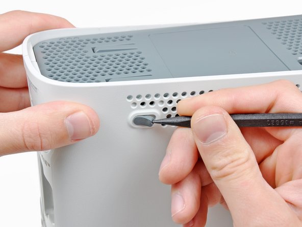
In the next few steps, you will use the tip of a spudger or the finger of an Xbox 360 opening tool to release the clips along the left and right sides of the bottom vent. Their locations are highlighted in red.
You will insert the tool into the holes molded into the white plastic side case pieces.
To release the clips, work from the front edge of the bottom vent.
While slightly lifting the front edge of the bottom vent, use the tip of a spudger to push the clips closest to the front of the bottom vent towards the inside of the console.
Stand the console vertically with the top edge facing up.
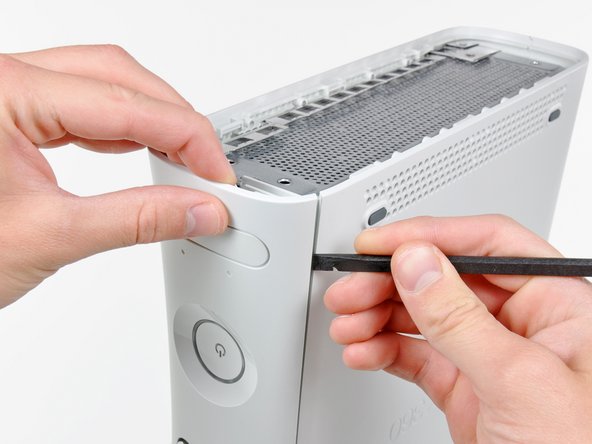
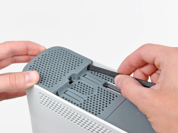
The top vent is secured to the console via clips. The first two clips are located underneath the top vent closest to the faceplate, as shown in the pictures.
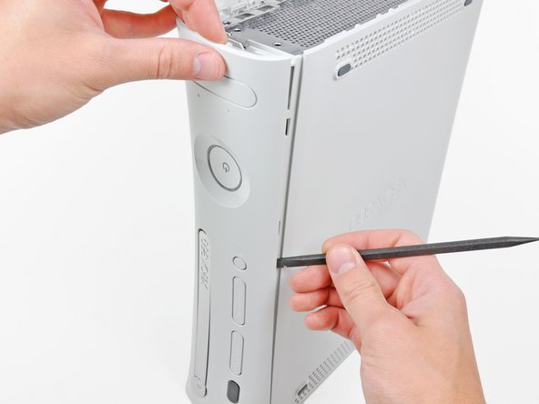
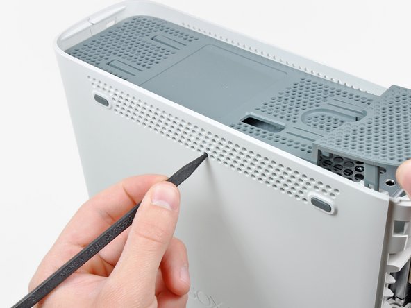
In the next few steps, you will use the tip of a spudger or the finger of an Xbox 360 opening tool to release the clips along the left and right sides of the top vent. Their locations are highlighted in red.
To release the clips, work from the middle of the top vent.
While slightly lifting the front edge of the top vent, use the tip of a spudger to push the clips closest to the center of the top vent towards the inside of the console.
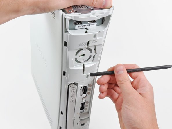
The upper and lower cases are attached via several latches, located in the front and back of the console. These latches must be disengaged to separate the upper case from the console.
Use the flat end of a spudger to release the following latches:
While pushing the upper and lower cases apart, use the tip of a spudger or the finger of an Xbox 360 opening tool to push the long clip highlighted in red toward the center of the 360.
The clip should release, leaving the clips near the power connector as the only thing holding the upper and lower cases together.
Insert your screwdriver parallel to the motherboard between the X clamp and its retaining post.
Twist the screwdriver to fully release the X clamp from its retaining post.
Repeat this process for all four corners of the X clamp.
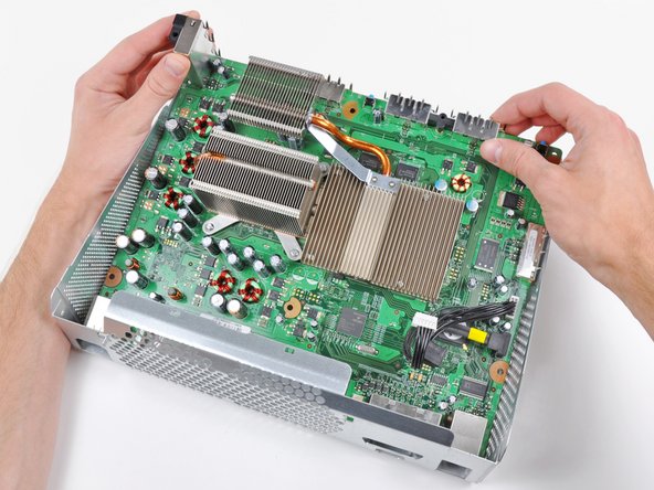
When removing the last corner of the X clamp and holding the motherboard upside down, be sure to catch the GPU heat sink to avoid damage from it falling.
To reinstall the X clamp, first start by attaching two corners to the posts on the heat sink.
While holding the third arm of the X clamp down against the post attached to the heat sink, use a small flathead screwdriver to pry the X clamp away from the heat sink post.
As you pry, press down on the arm of the X clamp until you "walk" it down into the retaining groove cut into the post attached to the heat sink.
Repeat this process for the fourth arm of the X clamp.
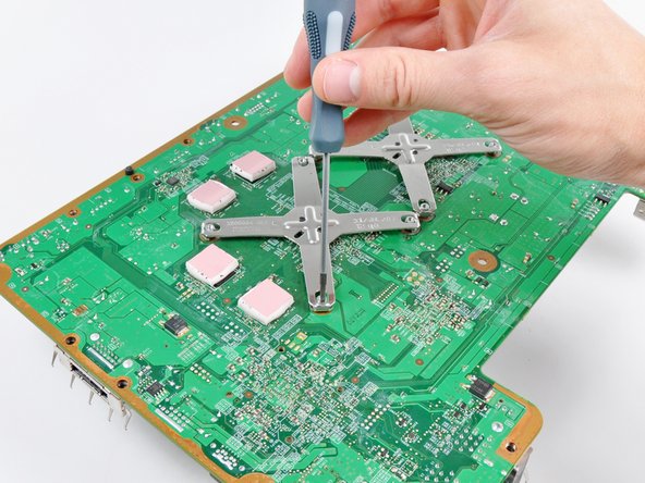
Insert the tip of a small flathead screwdriver between the X clamp and its retaining post on the heat sink.
Pry the X clamp away from its retaining post until it is lifted above the small groove cut into the retaining post.
If necessary, insert your screwdriver parallel to the motherboard between the X clamp and its retaining post. Twist the screwdriver to fully release the X clamp from its retaining post.
Repeat this process for all four corners of the X clamp.
When removing the last corner of the X clamp and holding the motherboard upside down, be sure to catch the CPU heat sink to avoid damage from it falling.
The X-clamps are not reused when installing the red ring of death fix kit.
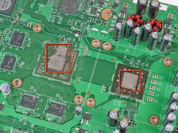
Now that the heat sinks are off both processors, use a plastic spudger to remove all of the old thermal paste residue from the faces of both processors and the inner faces of the heat sinks.
Work slowly as you remove the old residue, as many sensitive components are soldered near the processors. If damaged, you may need a whole new motherboard
It is best to use a solvent such as ArctiClean to dissolve the old thermal paste and remove all residue before applying new paste. Alternatively, you can use a mild solvent such as a high purity rubbing alcohol.
You can also use many classic dry-deoxidating sprays: spray it on the paste then rub it; you will remove the paste almost effortlessly and with no residues.
Now is also a good time to clean any dust out from between the fins of both heat sinks.
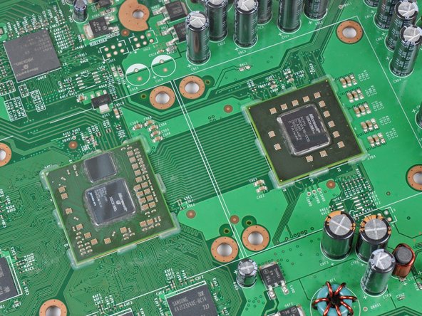
After cleaning, the mating faces of the heat sinks and the processors should look as shown.
Before proceeding any further, now is the perfect time to reflow the solder on the motherboard. Reflowing provides a higher chance of success in fixing red ring failures and is not hard to accomplish. All that is required is a heat gun. We have a guide that makes it easy.
This step is performed with the motherboard out of the chassis.
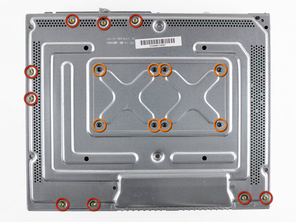
Insert a machine screw through each of the four holes around the CPU heat sink, with their heads on the back side of the board.
While holding the head of the screw, place a nylon washer then a metal washer over the threads.
The order of the washers is important. Do not put the metal washer on first.
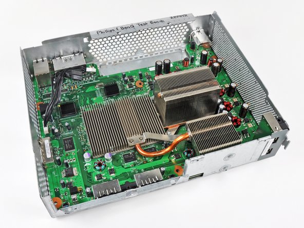
When attaching the CPU heat sink, be sure the fins are aligned with the air flow from the fans (as seen in the third picture). Having the flat side of the fins perpendicular to the air flow will cause your Xbox 360 to overheat.
Using the large flathead screwdriver bit, tighten the screws into the CPU heat sink. First lightly tighten the four screws in an X-shaped pattern as seen in the second picture, then follow the same X-shaped sequence to really torque the screws down.
Don't be afraid of over-tightening the screws - the pressure between the heat sinks and processors caused by sufficiently torqued screws is needed to squeeze the processors back against the board.
Repeat the same process to attach your GPU heat sink.
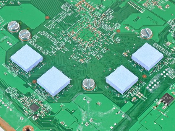
Use the edge of your small flathead screwdriver or another thin and sharp object to carefully pull up a corner of the blue or white plastic sheet covering the adhesive on the bottom of both heat sinks.
Be careful not to wrinkle or peel up the adhesive in the process.
Peel the protective sheets off the adhesive on both heat sinks.
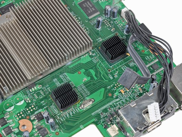
Lightly clean the surface of the two chips highlighted in red on the first picture.
Be sure to position the heat sinks correctly before you stick them down, as the adhesive is extremely strong and sensitive to being repositioned.
Stick the two heat sinks down against the top of the two chips highlighted in red on the first picture, being sure the fins are aligned as seen in the second picture.
When reinstalling the optical drive, be sure both the power and SATA cables do not interfere with the heat sink attached closest to their sockets on the motherboard.
I didn't have a heat gun so I disabled the fan and left the 360 on for 1/2 hour to heat up the weak solder points and then let it cool down for 1/2 hour before re-assembling the 360. This gave me all green lights.
When you take it apart, I recommend following our reflow guide before installing the RROD fix kit. I recently did this to an X360 that the RROD kit fixed only momentarily and afterwards it worked good as new.
I followed this guide and even performed the reflowing procedure. It worked perfectly. I noticed that when I took my Xbox 360 apart there were no existing thermal pads on the RAM chips on the underside of the mobo. Perhaps this caused the problem...? Either way this guide was thorough and easy to follow. Be sure to read ahead a step or two because some things are described generally in one step, then in better detail in the step after.