跳转到主内容

Sanyo VPC-T700 LCD Screen Replacement

你所需要的

  1. Sanyo VPC-T700 LCD Screen Replacement, LCD Screen: 步骤 1 中的图像 1,3 Sanyo VPC-T700 LCD Screen Replacement, LCD Screen: 步骤 1 中的图像 2,3 Sanyo VPC-T700 LCD Screen Replacement, LCD Screen: 步骤 1 中的图像 3,3
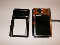
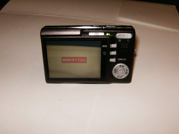
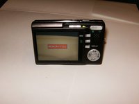
    • Cameras powers on and the broken LCD becomes immediately evident.
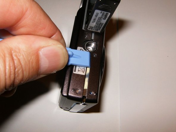
    • Remove the battery

    • Remove the camera strap

  2. Sanyo VPC-T700 LCD Screen Replacement: 步骤 2 中的图像 1,3 Sanyo VPC-T700 LCD Screen Replacement: 步骤 2 中的图像 2,3 Sanyo VPC-T700 LCD Screen Replacement: 步骤 2 中的图像 3,3
    • Remove the four screws on the right side of the camera

    • Remove the two screws on the left side.

    • remove the four screws on the bottom of the camera.

    • The two screws on the thread for a tripod are longer than the others, keep those separated.

  3. Sanyo VPC-T700 LCD Screen Replacement: 步骤 3 中的图像 1,3 Sanyo VPC-T700 LCD Screen Replacement: 步骤 3 中的图像 2,3 Sanyo VPC-T700 LCD Screen Replacement: 步骤 3 中的图像 3,3
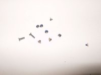
    • Here is a look at the screws from the camera. The two screws from the tripod thread are the longest.

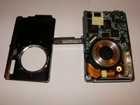
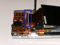
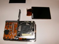
    • Start splitting the housing with either an opening tool or your fingernails. The housing does not require a lot of force and will easily unsnap.

    • The front cover seems to be easiest and will come off first

  4. Sanyo VPC-T700 LCD Screen Replacement: 步骤 4 中的图像 1,3 Sanyo VPC-T700 LCD Screen Replacement: 步骤 4 中的图像 2,3 Sanyo VPC-T700 LCD Screen Replacement: 步骤 4 中的图像 3,3
    • The rear cover can now be easily removed. The LCD is sitting in a frame without fasteners. It will just lift up, however, there will be a piece of insulating material that is separating the back of the LCD from the logic board. Remove this after the removal of the LCD from the frame. Do not try to remove the LCD from the PCB yet.

    • Open the ribbon cable connector by pulling the white clasp gently up.

    • Remove the old LCD.

  5. Sanyo VPC-T700 LCD Screen Replacement: 步骤 5 中的图像 1,2 Sanyo VPC-T700 LCD Screen Replacement: 步骤 5 中的图像 2,2
    • Here is the new LCD. Note the protective cover. Remove that cover by pulling on the green tab after installing the LCD to the PCB.

    • After reassembling your camera, hopefully it will look like this.

结论

To reassemble your device, follow these instructions in reverse order.

另外一个人完成了本指南。

oldturkey03

于09/29/10注册

781,527 声望

创作了119篇指南

团队

Global Fixers Global Fixers 的会员

Community

32 名成员

创作了531篇指南

0条评论

添加评论

浏览统计数据:

过去 24 小时: 0

过去 7 天: 0

过去 30 天: 1

总计 1,291