简介
Follow this guide to replace the screen and battery assembly on your Samsung Galaxy S21 Ultra.
This guide is written for the screen and battery assembly. The assembly consists of the screen, battery, and frame together in one part. Be sure you have the right part before you begin the repair.
If your battery is swollen, take appropriate precautions. Before disassembling your device, completely discharge the battery. This reduces the risk of a dangerous thermal event if the battery is accidentally damaged during the repair.
Note: Retaining water resistance after the repair will depend on how well you reapply the adhesive, but your device will lose its IP (Ingress Protection) rating.
你所需要的
-
-
Insert a SIM eject tool, bit, or straightened paper clip into the SIM card tray hole on the top edge of the phone.
-
Press the SIM eject tool into the SIM card tray hole to eject the SIM card tray.
-
Remove the SIM card tray.
-
-
-
Prepare an iOpener and apply it to the back cover for at least three minutes to loosen the adhesive underneath.
-
-
-
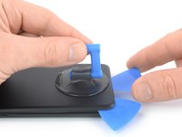
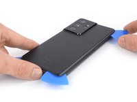
Secure a suction handle to the bottom edge of the back cover, as close to the edge as possible.
-
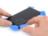
Lift the back cover with the suction handle to create a small gap between the back cover and the frame.
-
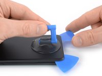
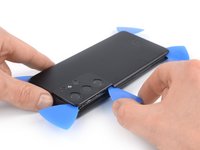
Insert an opening pick into the gap you created.
-
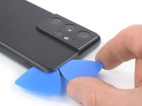
Slide the opening pick to the bottom left corner to slice the adhesive.
-
Leave the opening pick in place to prevent the adhesive from resealing.
-
-
-
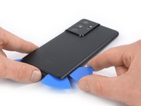
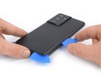
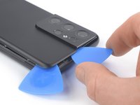
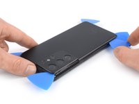
Insert a second opening pick at the bottom edge of your phone.
-
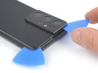
Slide the opening pick to the bottom right corner to slice the adhesive.
-
Leave the opening picks in place to prevent the adhesive from resealing.
-
-
在这个步骤中使用的工具:Tweezers$4.99
-
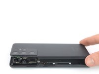
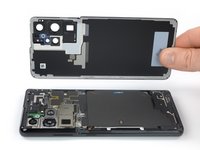
Remove the back cover.
-
This is a good point to power on your phone and test all functions before sealing it up. Be sure to power your phone back down completely before you continue working.
-
Remove any adhesive chunks with a pair of tweezers or your fingers. Apply heat if you're having trouble separating the adhesive.
-
If you're using custom-cut adhesives, follow this guide.
-
If you're using double-sided tape, follow this guide.
-
-
-
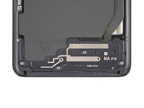
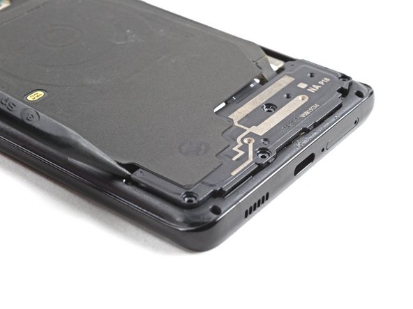
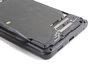
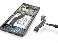
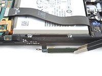
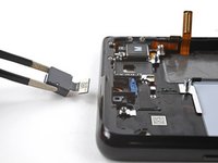
Insert an opening pick underneath the left bottom end of the NFC antenna and charging coil assembly.
-
Carefully slide the opening pick along the bottom left edge of the assembly to separate it from the battery.
-
-
-
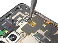
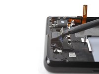
Use a spudger to disconnect the charging coil by prying the connector straight up from its socket.
-
-
-
Use a spudger to disconnect the NFC antenna by prying the connector straight up from its socket.
-
-
-
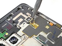
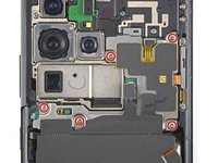
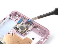
Use a Phillips screwdriver to remove the five 3.9 mm-long screws securing the NFC antenna and charging coil assembly.
-
-
-
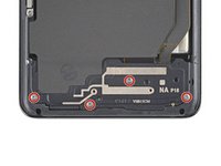
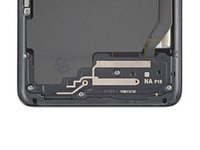
Use a Phillips screwdriver to remove the four 3.9 mm-long screws securing the loudspeaker assembly.
-
-
-
Insert the tip of a spudger between the frame and the upper-left notch in the loudspeaker.
-
Pry up with the spudger to release the loudspeaker from its plastic clips.
-
-
-
在这个步骤中使用的工具:Tweezers$4.99
-
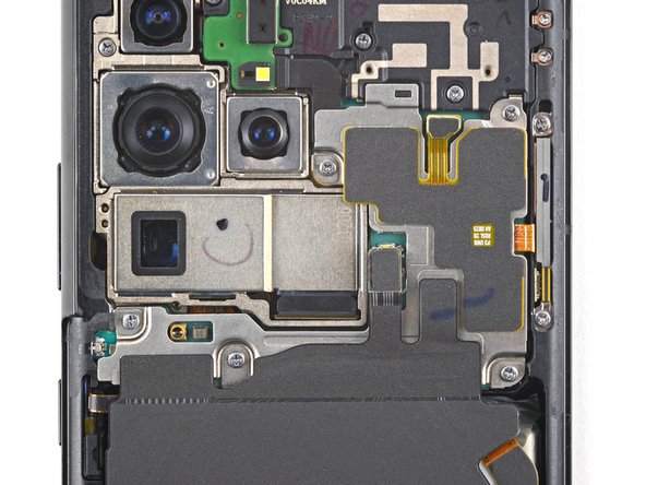
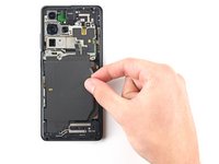
Use a pair of tweezers or your fingers to carefully remove the NFC antenna, charging coil, and loudspeaker assembly.
-
-
-
Use a spudger to pry up and disconnect the battery's press connector.
-
-
-
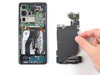
Use a spudger to pry up and disconnect the primary and secondary interconnect cables' press connectors on the motherboard.
-
-
在这个步骤中使用的工具:Tweezers$4.99
-
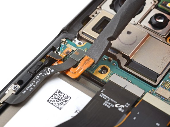
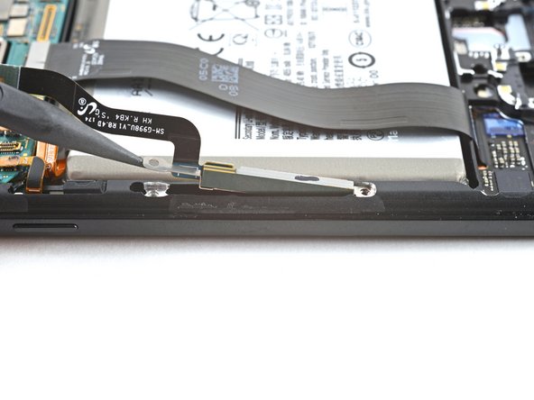
Use a spudger to disconnect the secondary interconnect cable from the daughterboard by prying its bottom connector straight up from its socket.
-
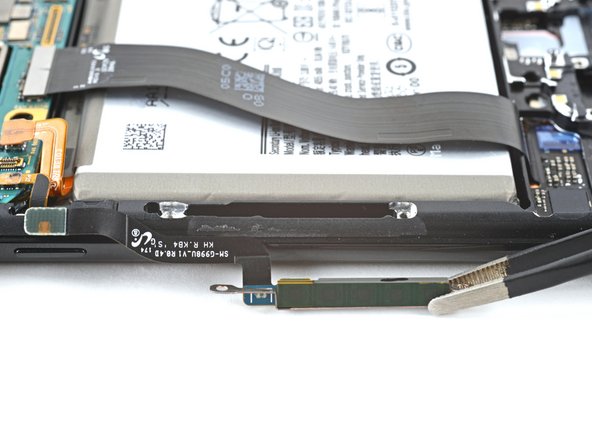
Use your fingers or a pair of tweezers to carefully remove the secondary interconnect cable.
-
-
-
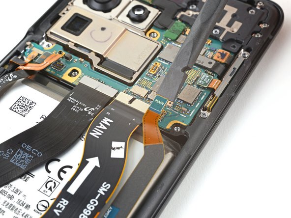
Use a spudger to disconnect the primary interconnect cable from the daughterboard by prying its bottom connector straight up from its socket.
-
Use your fingers or a pair of tweezers to carefully remove the primary interconnect cable.
-
-
-
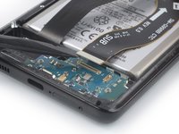
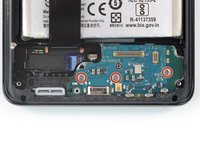
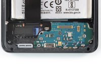
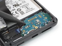
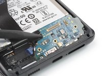
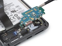
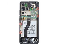
Use a Phillips screwdriver to remove the three 3.4 mm-long screws securing the charging board.
-
-
-
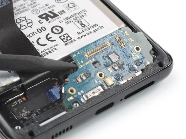
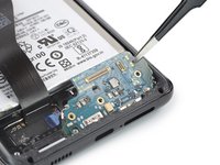
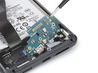
Insert the pointed end of a spudger underneath the left edge of the charging board next to the main flex cable connector.
-
Use your spudger to pry up the charging board.
-
-
在这个步骤中使用的工具:Tweezers$4.99
-
Use a pair of blunt tweezers or your fingers to remove the charging board. Start by lifting its top edge up and then carefully slide the USB-C connector out of its recess.
-
-
-
Use a spudger to pry up and disconnect the left 5G mmWave antenna's press connector.
-
-
-
Use a spudger to pry up and disconnect the right 5G mmWave antenna's press connector.
-
-
-
Use a Phillips screwdriver to remove the four 3.4 mm-long screws securing the 5G mmWave antennas.
-
-
在这个步骤中使用的工具:Tweezers$4.99
-
Use the point of a spudger to pry up on the right 5G mmWave antenna bracket's bottom screw tab.
-
Use tweezers, or your fingers, to remove the right 5G mmWave antenna.
-
-
-
Use the point of a spudger to pry up on the left 5G mmWave antenna bracket's bottom screw tab.
-
Use tweezers, or your fingers, to remove the left 5G mmWave antenna.
-
-
-
Use a Phillips screwdriver to remove the four 3.9 mm-long screws securing the earpiece speaker and laser AF module assembly.
-
-
-
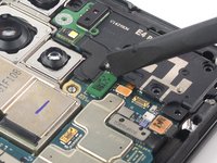
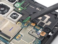
Use a spudger to disconnect the laser AF module and earpiece speaker flex cables by prying the connectors straight up from their socket.
-
-
-
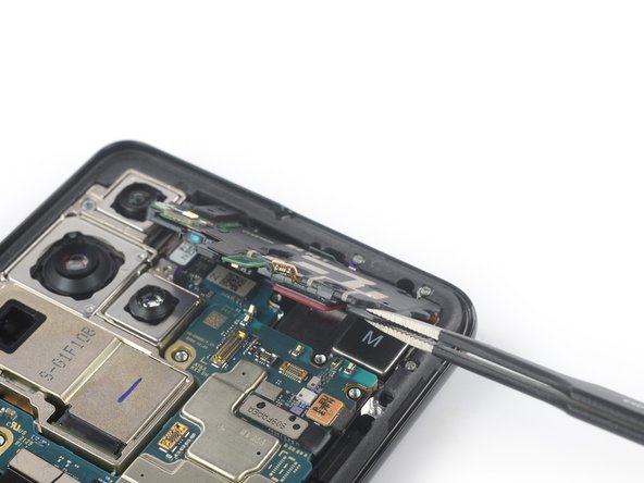
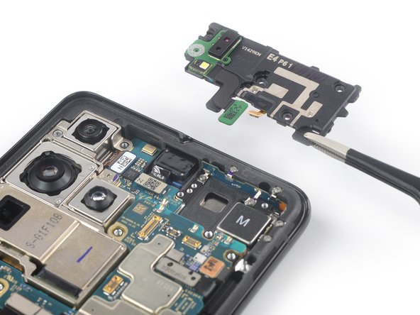
Grab the bottom right corner of the earpiece speaker and laser AF module assembly with a pair of blunt nose tweezers and carefully lift it upwards.
-
Remove the earpiece speaker and laser AF module assembly.
-
-
-
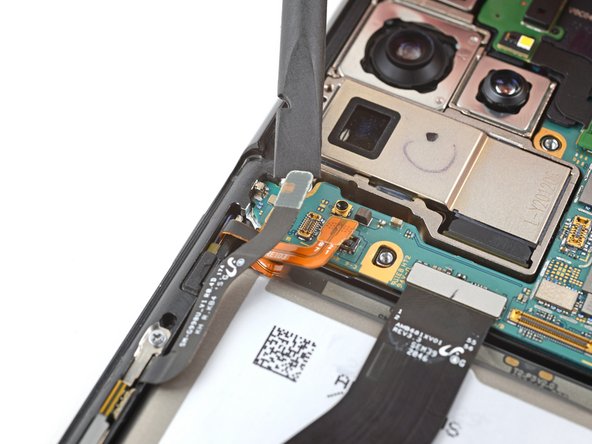
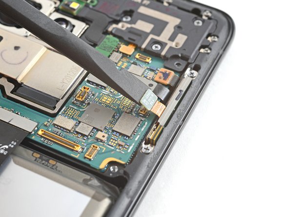
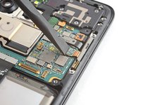
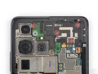
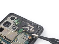
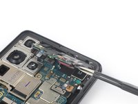
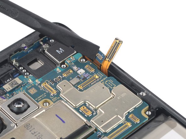
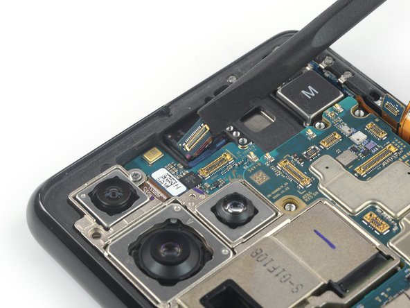
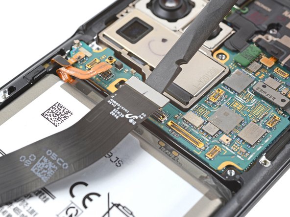
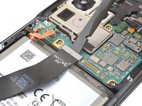
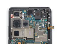
Use a spudger to disconnect the in-display fingerprint and antenna flex cables by prying the connectors straight up from their socket.
-
Carefully bend both connectors to the side to free the motherboard.
-
-
-
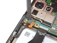
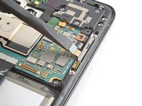
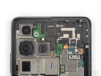
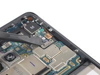
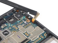
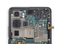
Use a spudger to disconnect the front facing camera cable by prying the connector straight up from its socket.
-
-
-
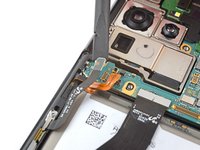
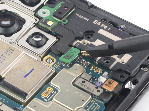
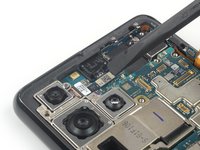
Use a spudger to disconnect the power button flex cable by prying the connector straight up from its socket.
-
Carefully bend the connector to the side to free the motherboard.
-
-
-
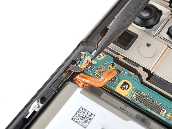
Use a spudger to pry up and disconnect the display cable's press connector.
-
-
-
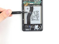
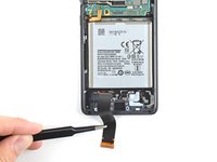
Use tweezers, or your fingers, to bend the display cable away from the device.
-
-
-
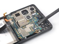
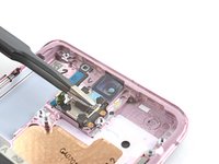
Use a Phillips screwdriver to remove the 3.9 mm-long screw securing the camera module.
-
-
-
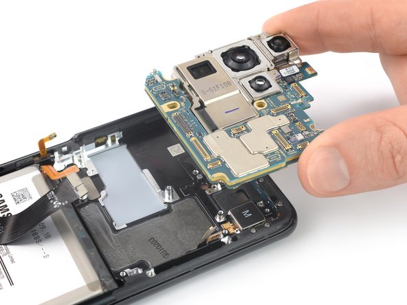
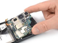
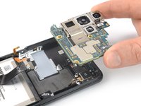
Insert an spudger underneath the top edge of the motherboard next to the vibration motor.
-
Twist the spudger to pry up and loosen the motherboard.
-
-
-
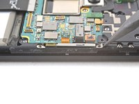
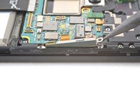
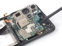
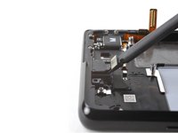
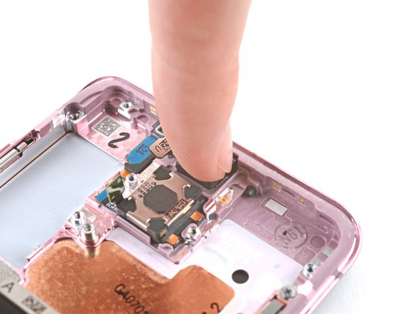
Insert a spudger into the gap between the frame and the front camera.
-
Pry up with the spudger to separate the front camera from the frame.
-
Use tweezers, or your fingers, to remove the front camera.
-
-
-
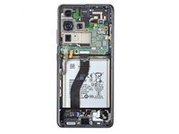
You're now left with the screen and battery assembly.
-
-
-
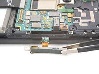
Peel off the front camera adhesive from its liner and apply the sticky end to the frame.
-
Use tweezers, or your fingers, to pull on the tab and expose the top layer of adhesive.
-
Insert the front camera and apply pressure to adhere it to the frame.
-


To reassemble your device, follow these instructions in reverse order.
Take your e-waste to an R2 or e-Stewards certified recycler.
Repair didn’t go as planned? Try some basic troubleshooting, or ask our Answers community for help.
To reassemble your device, follow these instructions in reverse order.
Take your e-waste to an R2 or e-Stewards certified recycler.
Repair didn’t go as planned? Try some basic troubleshooting, or ask our Answers community for help.
28等其他人完成本指南。


10条评论
How do we seal the back cover after replacing the screen? iFixit toolset does not come with glue or adhesive. It is not clear if the screen replacement part already has adhesive on it.
Save yourself a lot of hassle and don't separate the camera lens assy from the back cover. Then during reassembly withr pre-cut adhesive, cut that section away at the small lines indicated on the adhesive.
The back cover is glass... not plastic, so be careful..... use regular intervals of heat applications. Apply 10x the heat it says....
because the glue is strong. The older the phone the more stubborn the adhesive. Worse case scenario you might need to by the back cover.
We cracked ours a little but was reusable....
My screen replacement kit came with an adhesive cutout labeled as "G998 TAPE 3RD MIC HOLD TAPE". After much searching I was unable to find anywhere in these instructions or on the phone where it discussed using this adhesive. I am unsure where in the phone the adhesive goes. Clarification would be appreciated. I suspect it may go under the camera assembly but in these instructions that is removed whole with the motherboard so it may be an unnecessary item.
Thanks for the guide on how to replace the screen. My wife's S21 Ultra is working great and I look like the hero. My only suggestion is to add an how to add the Samsung adhesive strips and where they go. @john84651 Thanks for the tip on removing the adhesive from the antennas.