跳转到主内容
加入维修社区 - 创建账户

SNES 2CHIP 50/60 Hz Switchless Mod + LED Mod

你所需要的

    1. SNES 2CHIP 50/60 Hz Switchless Mod + LED Mod, Motherboard: 步骤 1 中的图像 1,1
      • Remove the two Phillips two 11.6mm screws that connect the front shield to the motherboard.

      添加评论

    2. SNES 2CHIP 50/60 Hz Switchless Mod + LED Mod: 步骤 2 中的图像 1,1
      • Lift the front shield straight up to remove it from the motherboard.

      询问修复机器人

      添加评论

    3. SNES 2CHIP 50/60 Hz Switchless Mod + LED Mod: 步骤 3 中的图像 1,1
      • Remove the two silver 15.6 mm Phillips #2 screws on either side of the 62 pin connector.

      询问修复机器人

      添加评论

    4. SNES 2CHIP 50/60 Hz Switchless Mod + LED Mod: 步骤 4 中的图像 1,1
      • Remove the 11.8 mm Phillips #2 screw near the rear of the SNES.

      询问修复机器人

      添加评论

    5. SNES 2CHIP 50/60 Hz Switchless Mod + LED Mod: 步骤 5 中的图像 1,1
      • Lift the motherboard straight up to remove it.

      添加评论

    1. SNES 2CHIP 50/60 Hz Switchless Mod + LED Mod, The Two Chips: 步骤 6 中的图像 1,1
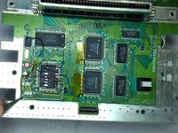
      • The Two Chips that you need on your Super Nintendo

      • This mod only works on original Super Nintendo with 2 Chips, this mod doesn't work on the 1 Chip Snes.

      询问修复机器人

      添加评论

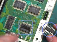
    2. SNES 2CHIP 50/60 Hz Switchless Mod + LED Mod, The Lockout Chip: 步骤 7 中的图像 1,2 SNES 2CHIP 50/60 Hz Switchless Mod + LED Mod, The Lockout Chip: 步骤 7 中的图像 2,2
      在这个步骤中使用的工具:
      Desoldering Pump
      $3.99
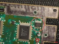
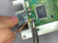
      • Remove the Lock Out chip (use the solder gun)

      • After removing the lock out chip there will probably be leftover of solder where the chip used to be so try to remove the soldier as good as you can

      • To remove the solder leftover, you can use the soldering iron and solder wick.

      询问修复机器人

      添加评论

    3. SNES 2CHIP 50/60 Hz Switchless Mod + LED Mod, PPU 2: 步骤 8 中的图像 1,2 SNES 2CHIP 50/60 Hz Switchless Mod + LED Mod, PPU 2: 步骤 8 中的图像 2,2
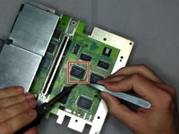
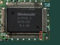
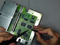
      • Lift up the PPU2 Pin 30 from the Motherboard

      询问修复机器人

      添加评论

    4. SNES 2CHIP 50/60 Hz Switchless Mod + LED Mod, PPU 1: 步骤 9 中的图像 1,2 SNES 2CHIP 50/60 Hz Switchless Mod + LED Mod, PPU 1: 步骤 9 中的图像 2,2
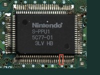
      • Now lift up Pin 24 on PPU 1

      询问修复机器人

      添加评论

    5. SNES 2CHIP 50/60 Hz Switchless Mod + LED Mod, Wire Time: 步骤 10 中的图像 1,1
      • Wire the lifted pins (PPU 2 Pin 30 & PPU1 Pin 24) together

      • You need to use a Soldering Iron to wire the pins together

      • You can also use tape to hold the wires down to the motherboard

      询问修复机器人

      添加评论

    6. SNES 2CHIP 50/60 Hz Switchless Mod + LED Mod, Program: 步骤 11 中的图像 1,1

      添加评论

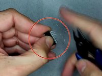
    7. SNES 2CHIP 50/60 Hz Switchless Mod + LED Mod, The Pins: 步骤 12 中的图像 1,3 SNES 2CHIP 50/60 Hz Switchless Mod + LED Mod, The Pins: 步骤 12 中的图像 2,3 SNES 2CHIP 50/60 Hz Switchless Mod + LED Mod, The Pins: 步骤 12 中的图像 3,3
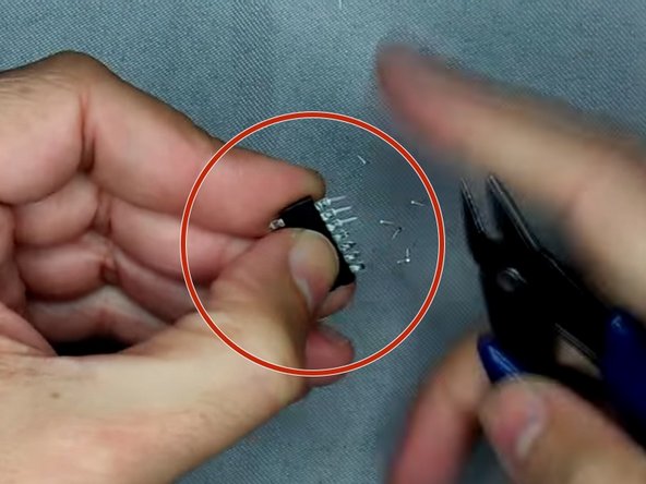
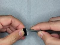
      • Bend the pins outwards

      • Then clip the pins

      • Use double sided tape and put it on top of the CPU and put the Super CIC on top of the double sided tape.

      询问修复机器人

      添加评论

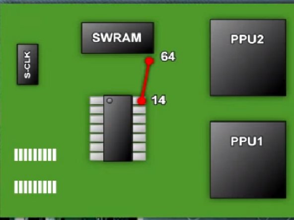
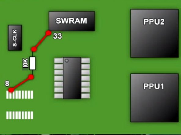
    8. SNES 2CHIP 50/60 Hz Switchless Mod + LED Mod, The Wires: 步骤 13 中的图像 1,3 SNES 2CHIP 50/60 Hz Switchless Mod + LED Mod, The Wires: 步骤 13 中的图像 2,3 SNES 2CHIP 50/60 Hz Switchless Mod + LED Mod, The Wires: 步骤 13 中的图像 3,3
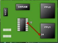
      • Pic 1: Solder a wire from Super CIC Pin 12 to PPU1 Pin 24

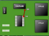
      • Pic 2: Solder a wire from Super CIC Pin 14 to SWRAM Pin 64

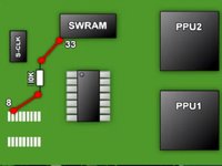
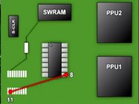
      • Pic 3: Solder the 10k Ohm Resistor to the pin 8 (where the old CIC used to be) and to SWRAM Pin 33

      添加评论

    9. SNES 2CHIP 50/60 Hz Switchless Mod + LED Mod, The Wires Part 2: 步骤 14 中的图像 1,3 SNES 2CHIP 50/60 Hz Switchless Mod + LED Mod, The Wires Part 2: 步骤 14 中的图像 2,3 SNES 2CHIP 50/60 Hz Switchless Mod + LED Mod, The Wires Part 2: 步骤 14 中的图像 3,3
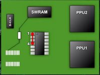
      • Pic 1: Solder a Wire from Super CIC Pin 1 to 4 on the same chip.

      • Pic 2: Solder a wire from Super CIC Pin 1 to the CPU Pin 1

      • Pic 3: Solder a wire from Super CIC Pin 13 to the End Point of the Resistor

      询问修复机器人

      添加评论

    10. SNES 2CHIP 50/60 Hz Switchless Mod + LED Mod, The Wires Part 3: 步骤 15 中的图像 1,3 SNES 2CHIP 50/60 Hz Switchless Mod + LED Mod, The Wires Part 3: 步骤 15 中的图像 2,3 SNES 2CHIP 50/60 Hz Switchless Mod + LED Mod, The Wires Part 3: 步骤 15 中的图像 3,3
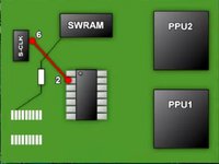
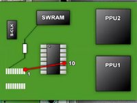
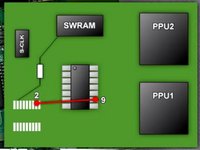
      • Pic 1: Sother a wire from Super CIC Pin 2 to S-CLK Pin 6

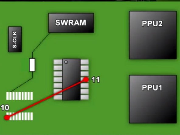
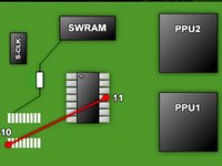
      • Pic 2: Sother a wire from Super CIC Pin 11 to Old CIC Pin 10

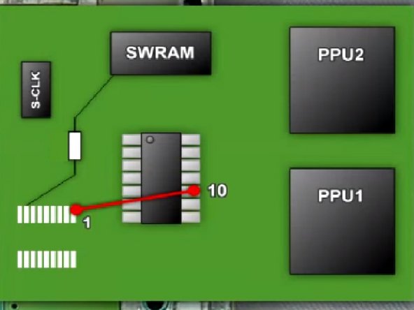
      • Pic 3: Sother a wire from Super CIC Pin 10 to Old CIC Pin 1

      询问修复机器人

      添加评论

    11. SNES 2CHIP 50/60 Hz Switchless Mod + LED Mod, The Wires Part 4: 步骤 16 中的图像 1,3 SNES 2CHIP 50/60 Hz Switchless Mod + LED Mod, The Wires Part 4: 步骤 16 中的图像 2,3 SNES 2CHIP 50/60 Hz Switchless Mod + LED Mod, The Wires Part 4: 步骤 16 中的图像 3,3
      • Pic 1: Solder a wire from Super CIC Pin 9 to Old CIC Pin 2

      • Pic 2: Solder a wire from Super CIC Pin 8 to Old CIC Pin 11

      • Pic 3: You've soldered most of the wires now, lets go to the LED Mod

      询问修复机器人

      添加评论

    12. SNES 2CHIP 50/60 Hz Switchless Mod + LED Mod, The LED Mod: 步骤 17 中的图像 1,3 SNES 2CHIP 50/60 Hz Switchless Mod + LED Mod, The LED Mod: 步骤 17 中的图像 2,3 SNES 2CHIP 50/60 Hz Switchless Mod + LED Mod, The LED Mod: 步骤 17 中的图像 3,3
      在这个步骤中使用的工具:
      Tweezers
      $4.99
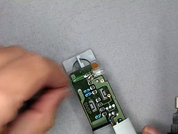
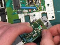
      • Plug out the controller ports and solder out the LED Light.

      • When the solder points have been desoldered, you can use the tweezers to pull out the led light

      • Sother on the new LED Light with the middle pin on the left solder hole

      • Do Not sother the middle pin on the LED Light to the right solder hole as it will then be stuck in only one color!

      询问修复机器人

      添加评论

    13. SNES 2CHIP 50/60 Hz Switchless Mod + LED Mod, Led Resistors: 步骤 18 中的图像 1,3 SNES 2CHIP 50/60 Hz Switchless Mod + LED Mod, Led Resistors: 步骤 18 中的图像 2,3 SNES 2CHIP 50/60 Hz Switchless Mod + LED Mod, Led Resistors: 步骤 18 中的图像 3,3
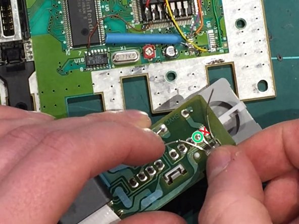
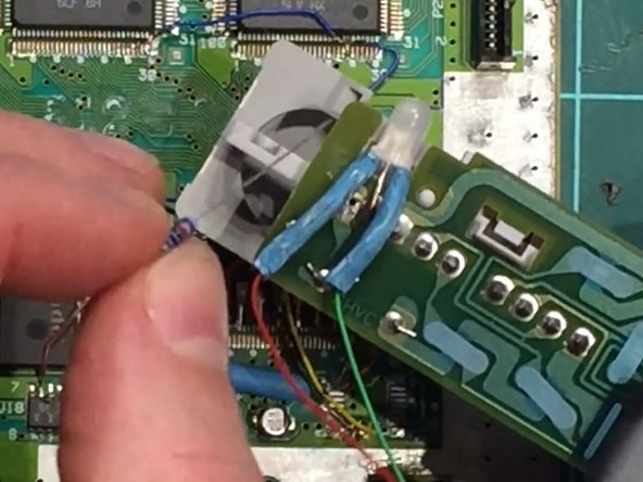
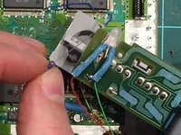
      • Solder 2 wires on the left and right pins on the led light, green wire on the left pin and red wire on the right pin.

      • After that you should put the wires into one heat shrink tube each, remember to heat the heat shrink tubes when its over the pins.

      • Then you have to solder the 2k Resistor to the red wire and the 220 ohm Resistor to the green wire.

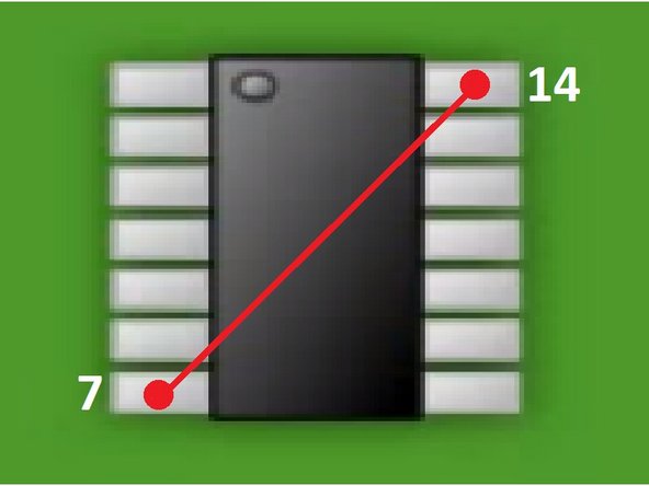
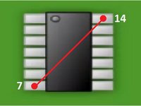
      • Then the last thing you need to do is to solder a wire from Super CIC Pin 7 to Pin 14.

      添加评论

    14. SNES 2CHIP 50/60 Hz Switchless Mod + LED Mod, The End: 步骤 19 中的图像 1,3 SNES 2CHIP 50/60 Hz Switchless Mod + LED Mod, The End: 步骤 19 中的图像 2,3 SNES 2CHIP 50/60 Hz Switchless Mod + LED Mod, The End: 步骤 19 中的图像 3,3
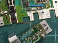
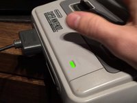
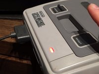
      • You're Now Done! You just need to put your Super Nintendo back together and then you have a Region Free Switchless Super Nintendo!

      • Green Light (PAL)

      • Red Light (NTSC) [For American and Japanese Games]

      • Orange Light (Auto)

      询问修复机器人

      添加评论

结论

To reassemble your device, follow these instructions in reverse order.

These screenshots have been taken by 2 videoes, one from Global Garage and Chips y Bits on YouTube! I made this guide since its a little easier to read a guide with pictures like this instead of watching a 30 min video

取消:我没有完成这个指南。

3等其他人完成本指南。

3指南评论

Lo hice tal y como dice el tutorial y la snes se quedó con la pantalla negra.

dragonero - 回复 分享
Is there some way to get a chip that is already programmed? I don’t have a plan on doing this a lot and the $100 is a bit much at the moment.

Brandon Vanoni - 回复 分享
Will this same method be used for the PAL version if the console.

Adrees Sattar - 回复 分享

添加评论

浏览统计数据:

过去 24 小时: 10

过去 7 天: 44

过去 30 天: 183

总计 21,710