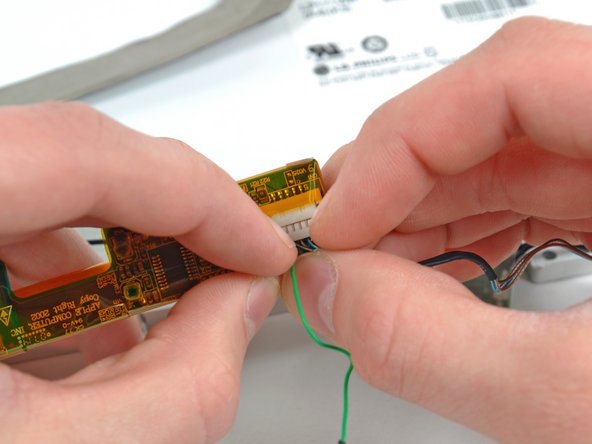
For this step, you only need to move the connector about 2 mm. Pulling too hard or too far will damage the connector.
Loosen the trackpad connector by pulling the locking bar toward the battery housing, using the tips of your fingers.
Slide the trackpad cable out of the loosened connector.
When reattaching the trackpad ribbon cable, make sure that the orange cable is slid into the connector above the locking bar.
Note: When reassembling the case, the trackpad cable can get stuck below the slot to the motherboard. It's possible to nudge it out slowly by gently prodding it on either side with a small screwdriver. You don't need to use much force to do this. Eventually it will just pop back out and you can reconnect as per the instructions above. Also, note that the locking bar comes loose so if you see a little piece of plastic lying around when reassembling, that's what it is. :)
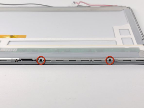
From each complete hinge assembly, remove two Torx T6 screws from the outside of each set, leaving two remaining in the middle of each hinge. On each side, the two screws closer to the edge of the computer are shorter than the two screws closer to the center of the computer. Then remove the two inner screws from each hinge assembly. There are 8 screws total.
When reassembling the display, check to see that the hinges are seated properly before reinstalling the 8 screws of the two hinges. There is a metal phalange on the inside end of each hinge assembly that must be pointed downward and fit into a slot below the inside edge of the hinge. If not, the inside end of each hinge will sit too high and the plastic retaining bracket for the wiring will not sit down properly.
The picture at left (rear panel already removed) shows the locations of the metal clips (shown in red) that snap on to the front display bezel. In the next few steps, you will use a small flathead screwdriver to release these clips from a ridge around the perimeter of the front display bezel.
When prying in the following steps, be sure not to damage the antenna cables that run around the perimeter of the front display bezel.
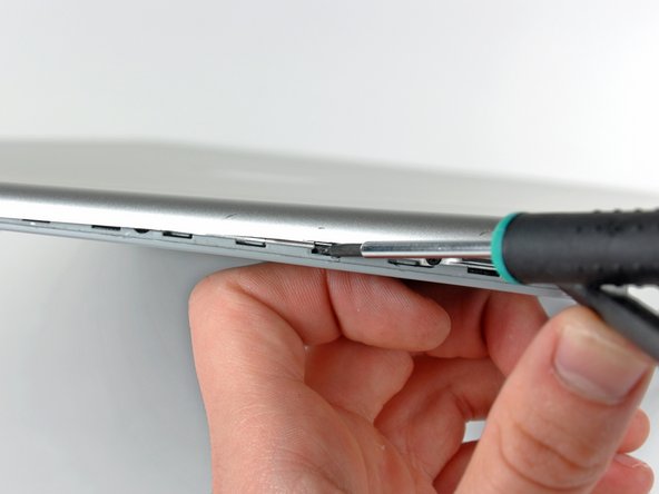
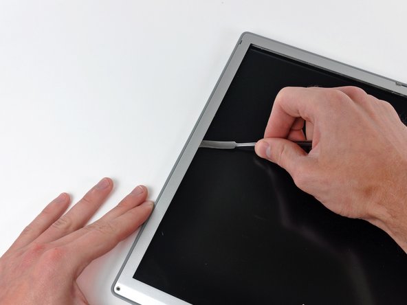
Insert the flat end of a spudger between the front display bezel and the plastic rim attached to the rear bezel near the lower right corner of the display.
Do not try to insert the spudger between the front display bezel and its plastic surround.
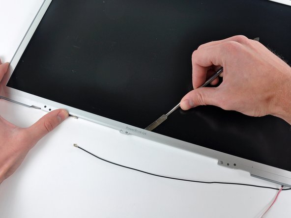
While carefully prying the rear display bezel away from the display assembly, use a small flathead screwdriver to pry the small steel clip nearest the bottom right corner of the display away from the edge of the front display bezel.
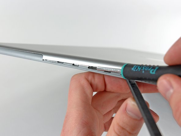
Repeat the above procedure until you've released all the clips along the right side of the display.
Insert the flat end of a spudger between the rear display bezel and the plastic surround of the front display bezel near the lower left corner of the display.
Carefully pry the rear display bezel away from the front display bezel to release a metal clip.
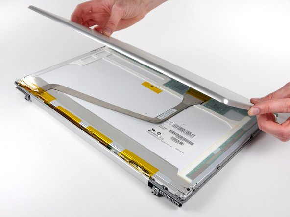
Slightly lift the lower edge of the rear display bezel and push it toward the top edge of the display, releasing the clips along the top edge of the rear display bezel.
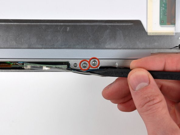
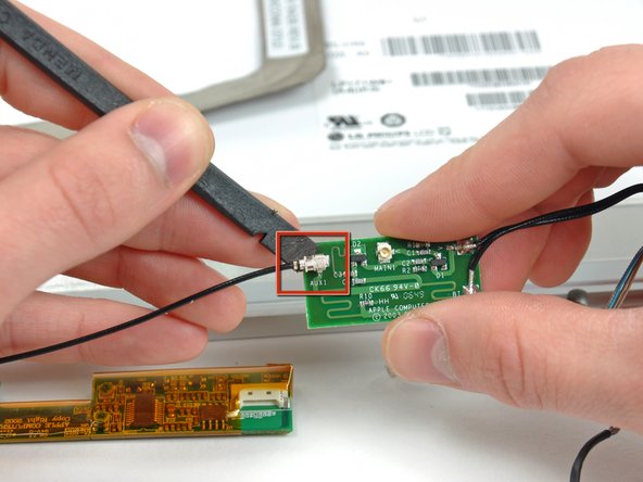
Carefully slide the display data cable out of its channel in the clutch hinges.
Repeat this process for the inverter/AirPort cables. Once the clutch hinge assembly is completely free from the display, lift it off the front display bezel.
In the following steps, you will use a heat gun to soften the adhesive securing the metal LCD frame to the front display bezel. Heat guns have the capability of producing an extremely hot jet of air, so be sure not to overheat the LCD panel.
With the heat gun set to low, start by heating the front display bezel near the upper left corner of the display panel.
Insert a plastic opening tool between the metal LCD frame and the front bezel.
Be sure you are prying between the metal LCD frame and the front bezel, not between the metal LCD frame and the LCD.
It may be necessary to reheat this area until the adhesive yields enough to insert the edge of a tool.
Use the flat end of a metal spudger to gently pry up the adhesive securing the metal LCD frame to the front bezel, taking special care not to scratch the LCD panel in the process.
While it is still inserted between the metal LCD frame and the front bezel, run the edge of your metal spudger along the top edge of the display to separate the adhesive securing the two pieces together, heating the area you are working on with a heat gun as necessary.
If the adhesive is hard to separate, use a heat gun to lightly heat the area you are working on.