简介
The IC (chip) inside the lamp seems to die slowly resulting in flickering/flashing lamp operation when using the radio. Also, the buttons may become unresponsive.
The problem occurs specifically when the device is cold and/or humid. Heating up the IC makes it work again.
你所需要的
-
-
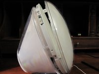
There is a screw under the shiny UL sticker. Remove the sticker or pierce it to unscrew and remove this bottom panel.
-
-
-
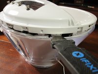
Flipping the light on its back will present a small section of the bezel that can be pried out. It is a small plastic strip with hooks that have to be disengaged to be removed.
-
Push the blade of the jimmy directly into the crevice above the cover. Once it has gone a few millimeters, tilt it to lift the cover slightly.
-
Slide the jimmy to the right side and press it against the latch to release it. Do the same for the left side.
-
-
-
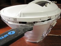
We can finally unscrew two more Philips head screws to remove the button ring.
-
Tip: Lift one end of the ring, tilting it toward the back of the alarm clock. That will get the hooks out from under the rear rim so you can start removing it..
-
-
-
-
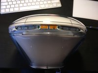
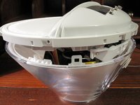
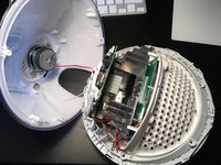
Now the six screws holding the front screen need to be removed and the screen can be pulled away to the front.
-
-
-
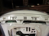
There are two tabs that hold the assembly in on the bottom left and right sides.
-
Using a jimmy — or any flexible, flat, metal tool, such as a putty knife — press the back tabs inwards to release.
-
-
-
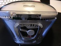
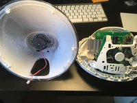
Disconnect the speaker from the main circuit board.
-
Loosen the screw and washer inside the back cover by the speaker and unwrap the antenna wire that was pinned underneath. Pull the antenna all the way through so the back cover can be removed.
-
-
-
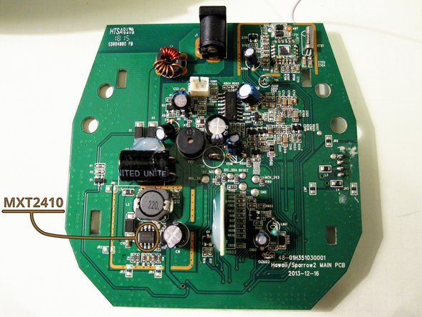
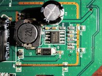
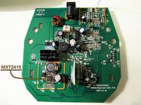
On the main PCB with the power jack, replace the MXT2410 switchmode regulator IC (SO-8 Package).
-
Currently a seller "adeleparts2010" has this chip available (might change in future). The previously recommended pin-compatible device from Quorvo (ACT4060ASH-T) is not a good choice and might cause more damage.
-


Work off the steps in reverse order to reassemble your device.
Work off the steps in reverse order to reassemble your device.
23等其他人完成本指南。
团队

41条评论
Hi Thomas,
I have the same problem, but i do not understand what you are doing with the R3 and R4. If i remove R4, with what should i replace it?
Or how should i measure it?
Thanks in advance,
Arnoud
I can only do it in Germany
Hallo Thomas,
ich finde das ist eine tolle Anleitung zur Reparatur des Lichtweckers. Ich hatte mich auch auf den Austausch des MXT2410 konzentriet. Es kam dann aber doch anders. Nach ca. 2-3 Wochen warten auf den ACT4060 war dieser schnell eingebaut. Das Ergebnis war enttäuschend. Keine Änderung, die 5V waren nicht messbar. Bei der weiteren Fehlersuche stellte ich fest, dass der ACT4060 und die zugehörige Drossel schnell warm wurden. Jetzt ging es an die Suche nach einem Kurzschlußkandidaten. Er war dann schnell gefunden: D3 (SK24). Eine andere Schottkydiode eingebaut (diesmal aus der Bastelkiste) und es wurde wieder Licht und Musik.
Freundliche Grüße,
Roland