当前版本的文档还未经巡查,您可以查看最新的已查核版本 。
移除两颗将电池后盖固定的梅花螺丝。
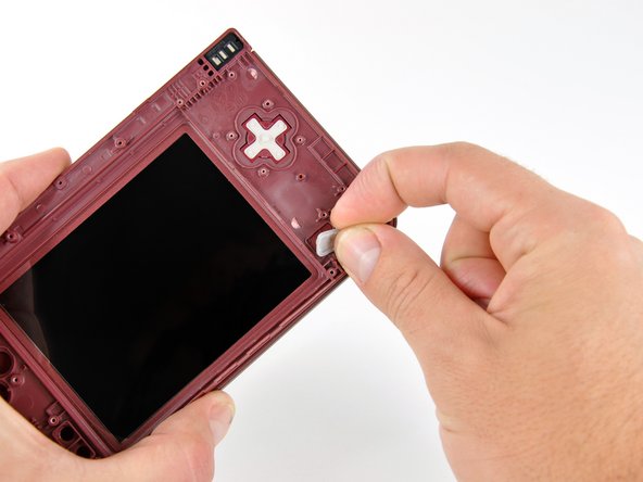
从DSi XL上提起电池后盖。
Using the flat end of a spudger, flip up the retaining flap on the camera ribbon ZIF connector.
Use the pointed end of a spudger to pull the camera ribbon from the ZIF connector.
Using the flat end of a spudger, flip up the retaining flap on the touchscreen cable ZIF connector.
With the pointed end of the spudger, pull the touchscreen cable from its connector on the motherboard.
Using the flat end of a spudger, flip up the retaining flap on the backlight cable ZIF connector.
With the pointed end of the spudger, pull the backlight cable from its connector on the motherboard.
Using the flat end of a spudger, flip up the retaining flap on the lower display data cable ZIF connector.
With the pointed end of the spudger, pull the lower display data cable from its connector on the motherboard.
Using the flat end of a spudger, flip up the retaining flap on the ZIF connector for the D-Pad/power button cable.
With the pointed end of the spudger, pull the D-Pad/power button cable from its connector on the motherboard.
Remove the screws securing the motherboard to the upper case:
A single 2.5 mm silver Phillips screw
Four 3.7 mm black Phillips screws
Using the flat end of a spudger, flip up the retaining flap on the upper display data cable ZIF connector.
With the pointed end of the spudger, pull the upper display data cable from its connector on the underside of the motherboard.
The motherboard is now free from the upper case.
With the console still upside-down, open the DSi XL slightly.
Push the lower display away from the upper case.
Remove the lower display from the DSi XL.
Turn the DSi XL over and open the display.
When re-assembling the device, be sure to re-install the ABXY and Start/Select buttons, as they are likely to fall out once the handheld console is turned over.
Use a pushpin to remove the four plastic screw covers on the front bezel.
Insert a spudger into the gap between the front and rear bezel.
Rotate the spudger away from the DSi XL, prying the two bezels apart.
Pull the Wi-Fi antenna cable through the right hinge connecting the front bezel and upper case.
Use the pointed end of a spudger to guide the connector at the end of the Wi-Fi antenna cable through the hinge.
To replace the antenna, use a pair of tweezers to guide the connector through the hinge.
Close the DSi XL and turn it over.
Using a pair of tweezers, pull the microphone out of its housing in the front bezel.
De-route the microphone cable, and pull it through the right hinge.
Using the flat end of a spudger, pry the left speaker out of its socket on the front bezel.
De-route the speaker cable along the top edge of the screen.
Work carefully and slowly, holding onto the wire and not the speaker itself. The solder joints may break if pulled on too hard.
In the same manner described above, remove the right speaker from its socket on the front bezel.
Place both speakers on the back of the upper LCD.
Ensuring that the upper LCD does not fall out of the front bezel, turn the DSi XL over.
Remove the seven 2.5 mm silver screws securing the power board to the upper case.
Lift the power board up off the upper case.
Open the case slightly.
Push the D-pad up through its housing in the upper case. Remove the D-pad.
In the same way, remove the power button from the upper case.
In the following steps, you will be using a spudger to remove the hinge pin from the left side of the DSi XL.
Place the tip of a spudger in the LED diffuser compartment, on the face of the clutch hinge.
Push the clutch hinge to the left.
Some force will be required. You will hear an audible "pop" when the clutch has cleared the lower case. It will move about 0.25".
Lift the left side of the front bezel away from the upper case.
Do not lift too far, or else the hinge pin will break. Only lift enough to clear the LED compartment, about 1".
Pull the front bezel to the left, separating the front bezel from the upper case.
Do not attempt to fully separate the two halves yet. There are still ribbon cables running through the upper case.
Grasp the camera and upper LCD ribbon cables between your thumb and forefinger, pulling them out of the upper case slightly, slide them down through the slit in the upper case.
Rotate the front bezel assembly clockwise so that the ends of the camera and LCD cables slide sideways through the slit in the front bezel.
In order to remove the upper LCD and the cameras from the front bezel, it is helpful to coil the ribbon cables together.
Carefully coil the two ribbon cables together, so that the connectors are on the inside of the spool.
Wrap the ribbon cables tightly, but not too tight, as bending the connectors will render them inoperable.
Holding the upper LCD and the cameras together, pull the cables through the hinge in the front bezel.
Pull slowly, making sure that the cables do not catch on the hinge pin and tear.
Uncoil the ribbon cables.
嵌入本指南
选择一个尺寸并复制下面的代码,将本指南作为一个小插件嵌入到你的网站/论坛中。
单个步骤
完整指南
小——600像素
中——800像素
大——1200像素
预览