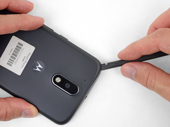
Insert a fingernail or a spudger into the notch on the bottom edge of the phone, near the charge port.
Gently twist or pry to open a small gap between the back cover and the body of the phone.
While keeping your tool (or fingernail) inserted into the gap between the back cover and the body of the phone, slide it around the corner to begin loosening the plastic clips holding the cover in place.
Insert a thin tool (such as one of your tweezer tips) under the red and black battery wires, and slide it underneath the battery connector.
Gently pry straight up to disconnect the battery.
Pry only from the side where the wires attach to the connector—if you pry anywhere else, you may break the socket.
During reassembly, align the connector in its socket with the exposed copper wire facing up, and then press straight down to reconnect it, wiggling slightly as you press to help it seat correctly.
Peel up the black pull tab at the top of the battery, and pull slowly but firmly to separate the battery from the adhesive holding it in place.
The battery separates more easily if you add a few drops of isopropyl alcohol along each side, to soften the adhesive beneath. High concentration (90% or greater) alcohol will not harm your phone's components.
Heating the area behind the battery can also help soften the adhesive, but be very careful not to overheat the battery.
If the pull tab breaks, use a spudger or an old credit card to pry up carefully on the edges of the battery until it comes loose.
Don't deform or puncture the battery—it can catch fire and/or explode if damaged.
Never reinstall a damaged or deformed battery. Replace the battery.
During installation, note the orientation of the battery—if the connector is on the same side as the motherboard, and the text is upside-down relative to the rest of the phone, you've done it correctly.
Use a few strips of thin double-sided adhesive tape or a pre-cut adhesive card to secure the battery. (Or, if you are replacing the display, it may come with adhesive for the battery pre-installed.)
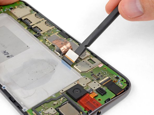
Peel up the copper tape covering the display connector.
This tape provides protection from electromagnetic interference. Keep it in one piece if possible, and carefully fold it back into position when your repair is complete.
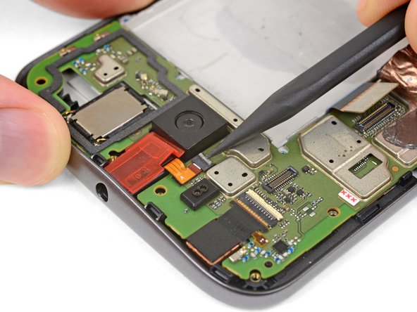
Pry up with your spudger to flip open the locking flap on the headphone jack's ZIF connector.
It's possible to disconnect the headphone jack at this point by pulling its orange flex cable straight out of the ZIF socket, but it's easy to tear the cable if you're not careful. For a better method, continue with the steps below.
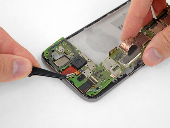
Grasping the motherboard by its edges, left the bottom end up at an angle, while keeping the top edge close to the phone.
Use your spudger to pry up the front-facing camera and make sure it separates safely from the frame. The camera can remain attached to the motherboard.
Using your tweezers, grasp the headphone jack flex cable and carefully pull it out of its socket as you remove the motherboard.
Remove the motherboard.
If you feel any resistance, stop. Make sure there are no components still holding the frame to the motherboard.
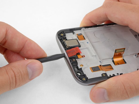
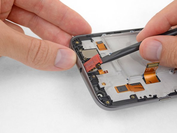
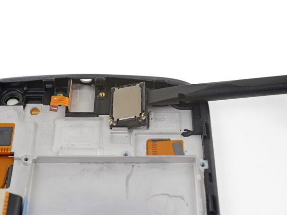
Using the flat of your spudger, pry up on the upper right edge of the earpiece speaker to separate it from the frame.
Strong adhesive secures the earpiece speaker. If necessary, apply heat or a few drops of isopropyl alcohol to help weaken the adhesive and make it easier to remove.
Check the condition of the adhesive around the bottom of the earpiece speaker when you reinstall it. A little heat from a hair dryer or iOpener can help soften the adhesive and make it sticky again. Be careful not to touch or damage the surface of the speaker.
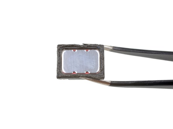
In some of the previous photos in this guide, the speaker is shown installed incorrectly. During installation, make sure the speaker's two spring contacts are located at the bottom corners, as shown in the first image in this step. Images showing the speaker rotated 180° (with the spring contacts near the top edge of the phone) are incorrect.
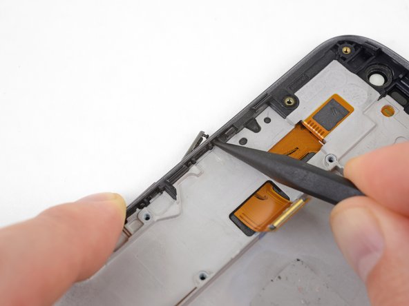
Wedge the sharp edge of your iFixit opening tool between the headphone jack flex and the plastic frame it's adhered to.
Carefully press down to separate the headphone jack flex cable from the adhesive securing it.
Don't use too much force, or you may damage the flex cable. If necessary, apply heat or a few drops of isopropyl alcohol to help weaken the adhesive and make it easier to remove.
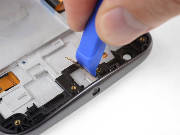
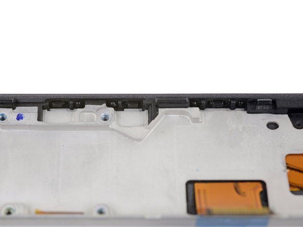
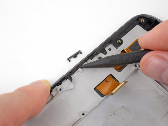
Push the power button out of the frame from the inside by carefully pressing the tip of your spudger against the tops of the two mushroom pins securing it.
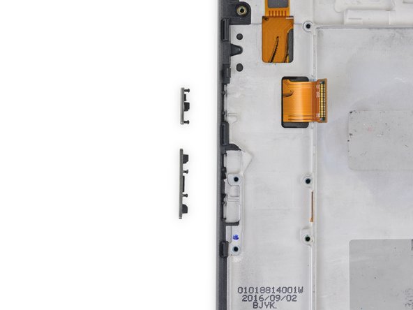
Only the LCD screen and digitizer assembly (with frame) remains.
Check carefully to make sure your replacement part matches, and that you've removed all the necessary parts from the old frame for installation in the new one.
I would not recommend it. The adhesive between the screen and the frame was too strong for me to separate, so a screen with a new frame pre-installed would be a better bet.