跳转到主内容

当前版本的文档还未经巡查,您可以查看最新的已查核版本

你所需要的

  1. , 底壳: 步骤 1 中的图像 1,1
    • 拆下以下十个将背板固定在上壳上的螺丝:

    • 三颗13.5mm十字螺丝。

    • 七颗3mm十字螺丝。

  2. : 步骤 2 中的图像 1,2 : 步骤 2 中的图像 2,2
    • 将手指s塞入入下壳体和通风口之间,向上提起将夹紧下壳体的夹子离开上壳体上。

    • 移走后壳。

  3. 这个步骤还没有翻译 帮忙翻译一下

    : 步骤 3 中的图像 1,3 : 步骤 3 中的图像 2,3 : 步骤 3 中的图像 3,3
    • Whenever working near the logic board, it is always wise to first disconnect the battery to avoid short circuits.

    • If present, grab the plastic tab attached to the battery connector and pull it toward the front edge of the device. For Late-2011 models the battery connector will not have a tab and is simply a plug that inserts straight down into the motherboard--to remove pry the plug straight up.

    • If the plastic tab is missing, use a spudger to pry the connector up from its socket.

    • Pull the tab parallel to the face of the logic board.

  4. 这个步骤还没有翻译 帮忙翻译一下

    : 步骤 4 中的图像 1,3 : 步骤 4 中的图像 2,3 : 步骤 4 中的图像 3,3
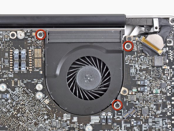
    • Use the flat end of a spudger to lift the right fan connector out of its socket on the logic board.

    • It is useful to twist the spudger axially from beneath the fan cable wires to release the connector.

    • The fan socket and the fan connector can be seen in the second and third pictures. Be careful not to break the plastic fan socket off the logic board as you use your spudger to lift the fan connector straight up and out of its socket. The layout of the logic board shown in the second picture may look slightly different than your machine but the fan socket is the same.

  5. 这个步骤还没有翻译 帮忙翻译一下

    : 步骤 5 中的图像 1,1
    • Remove the three 3.1 mm Phillips screws securing the right fan to the logic board.

    • In the Late 2011 MacBook Pro 17" Unibody these screws will be T6 Torx.

  6. 这个步骤还没有翻译 帮忙翻译一下

    : 步骤 6 中的图像 1,1
    • Remove the right fan from the upper case, minding its cable that may get caught.

  7. 这个步骤还没有翻译 帮忙翻译一下

    : 步骤 7 中的图像 1,1
    • Use the flat end of a spudger to lift the left fan connector out of its socket on the logic board.

    • It is useful to twist the spudger axially from beneath the fan cable wires to release the connector.

  8. 这个步骤还没有翻译 帮忙翻译一下

    : 步骤 8 中的图像 1,2 : 步骤 8 中的图像 2,2
    • Remove the three 3.1 mm Phillips screws securing the left fan to the logic board.

    • Remove the left fan from the upper case, minding its cable that may get caught.

  9. 这个步骤还没有翻译 帮忙翻译一下

    : 步骤 9 中的图像 1,2 : 步骤 9 中的图像 2,2
    • Use the tip of a spudger or your fingernail to flip up the retaining flap on the keyboard backlight ribbon cable.

    • Be sure you are prying up on the retaining flap, not the socket itself.

    • Pull the keyboard backlight ribbon cable out of its socket.

  10. 这个步骤还没有翻译 帮忙翻译一下

    : 步骤 10 中的图像 1,1
    • Before disconnecting the camera cable, a small plastic retainer stuck to the logic board must first be moved out of the way.

    • Use the tip of a spudger to push the small plastic cable retainer away from the camera cable socket for enough clearance to remove the camera cable.

  11. 这个步骤还没有翻译 帮忙翻译一下

    : 步骤 11 中的图像 1,1
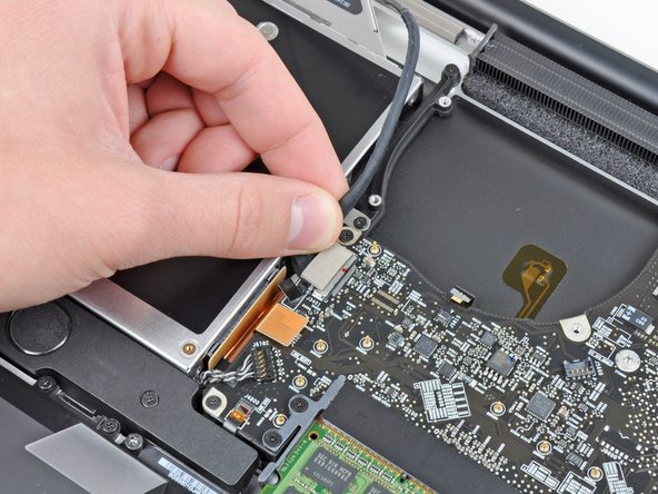
    • Pull the camera cable toward the optical drive opening to disconnect it from the logic board.

    • The camera cable socket is very fragile. Do not apply any upward force to this socket, as it may break off the logic board. Pull the camera cable parallel to the face of the logic board.

  12. 这个步骤还没有翻译 帮忙翻译一下

    : 步骤 12 中的图像 1,1
    • Use the flat end of a spudger to pry the optical drive connector up and out of its socket on the logic board.

  13. 这个步骤还没有翻译 帮忙翻译一下

    : 步骤 13 中的图像 1,1
    • Use the flat end of a spudger to lift the subwoofer & right speaker connector out of its socket on the logic board.

    • Pry up from beneath the wires.

  14. 这个步骤还没有翻译 帮忙翻译一下

    : 步骤 14 中的图像 1,2 : 步骤 14 中的图像 2,2
    • Use the tip of a spudger or your fingernail to flip up the retaining flap on the IR sensor ribbon cable socket.

    • Be sure you are prying up on the retaining flap, not the socket itself.

    • Pull the IR sensor ribbon cable out of its socket.

  15. 这个步骤还没有翻译 帮忙翻译一下

    : 步骤 15 中的图像 1,3 : 步骤 15 中的图像 2,3 : 步骤 15 中的图像 3,3
    • Remove the following four screws:

    • Two 3.5 mm Phillips screws

    • These may be T5 Torx screws in the Early 2011 model

    • Two 1.6 mm Phillips screws

    • Remove both connector shields from the logic board.

  16. 这个步骤还没有翻译 帮忙翻译一下

    : 步骤 16 中的图像 1,1
    • Use the flat end of a spudger to pry the trackpad connector up and out of its socket on the logic board.

  17. 这个步骤还没有翻译 帮忙翻译一下

    : 步骤 17 中的图像 1,2 : 步骤 17 中的图像 2,2
    • Use your fingernail to flip up the retaining flap on the keyboard ribbon cable socket.

    • Be sure you are prying up on the retaining flap, not the socket itself.

    • Pull the keyboard ribbon cable out of its socket.

    • For reassembly, it can be helpful to put a small piece of tape on the keyboard ribbon cable (being careful not to stick any to the contacts), to create a small handle. Align the cable with the socket and gently pull with the tape to fully seat it.

  18. 这个步骤还没有翻译 帮忙翻译一下

    : 步骤 18 中的图像 1,2 : 步骤 18 中的图像 2,2
    • Use your fingernail to flip up the retaining flap on the express card cage ribbon cable socket.

    • Be sure you are prying up on the retaining flap, not the socket itself.

    • Pull the express card cage ribbon cable out of its socket.

  19. 这个步骤还没有翻译 帮忙翻译一下

    : 步骤 19 中的图像 1,1
    • Use the flat end of a spudger to lift the hard drive cable connector up and out of its socket on the logic board.

  20. 这个步骤还没有翻译 帮忙翻译一下

    : 步骤 20 中的图像 1,2 : 步骤 20 中的图像 2,2
    • Use the tip of a spudger or your fingernail to flip up the retaining flap on the battery indicator cable socket.

    • Be sure you are prying up on the retaining flap, not the socket itself.

    • Pull the battery indicator ribbon cable out of its socket.

  21. 这个步骤还没有翻译 帮忙翻译一下

    : 步骤 21 中的图像 1,3 : 步骤 21 中的图像 2,3 : 步骤 21 中的图像 3,3
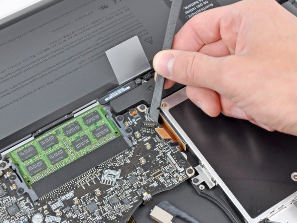
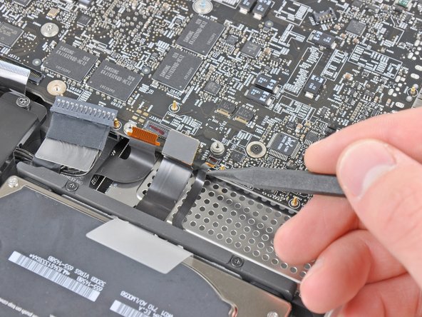
    • Lift the black plastic flap attached to the display data cable retainer and rotate it toward the DC-In side of the MacBook.

    • Pull the display data cable out of its socket.

    • The display data cable socket is very fragile. Do not lift the connector upward as you disconnect it, as the socket may break off the logic board. Pull the cable parallel to the face of the logic board.

  22. 这个步骤还没有翻译 帮忙翻译一下

    : 步骤 22 中的图像 1,1
    • Remove the following eight screws securing the logic board and DC-In board to the upper case:

    • Six 3.2 mm Phillips screws

    • These may be T6 Torx screws on the Early 2011 model.

    • Two 7.6 mm Phillips screws

  23. 这个步骤还没有翻译 帮忙翻译一下

    : 步骤 23 中的图像 1,2 : 步骤 23 中的图像 2,2
    • Handle the logic board assembly by its edges only.

    • Lift the logic board assembly from the side nearest the optical drive and lift it away from the upper case.

    • Note that you'll be removing the logic board and DC-in board together.

    • Carefully pull the ports and DC-In board away from the side of the upper case and remove the logic board assembly, minding any cables that may get caught.

  24. 这个步骤还没有翻译 帮忙翻译一下

    : 步骤 24 中的图像 1,1
    • Remove the eight 8.3 mm Phillips screws securing the heat sink to the logic board.

    • Be sure to keep track of the springs held under each of the screws.

  25. 这个步骤还没有翻译 帮忙翻译一下

    : 步骤 25 中的图像 1,1
    • Squeeze the heat sink thermal sensor cable between your thumb and the tip of a spudger.

    • Lift the spudger upward to lift the thermal sensor connector out of its socket on the logic board.

    • The early 2011 model may not have a thermal sensor connector.

  26. 这个步骤还没有翻译 帮忙翻译一下

    : 步骤 26 中的图像 1,1
    • Remove the heat sink from the logic board.

    • If the heat sink appears to be stuck to the logic board after removing all eight screws, it may be helpful to use a spudger to separate the two components.

    • If you need to mount the heat sink back onto the logic board, we have a thermal paste guide that makes replacing the thermal compound easy.

终点

33等其他人完成本指南。

10条评论

After compleating this repair , my mac had the normal hard drive noise then a chime did not even grey screen . almost instantly I smelt fire and saw smoke pouring out of the case.. maac was on battery at the time .. I opened it up and disconected the battery and then I saw the video display cable (Step 21 ) it had glowing embers on the tape and tottally melted one side of it ... the connector to the logic board has black marks , but i do not know if the damage is extened to the logic board or if I can get away with a new dispay data cable , dont even know where to source one here in NZ .. any help would be great

kevinleroy - 回复

I completed this guide. When I finished the macbook would not turn on => PANIC

I went over and the problem was the keyboard cable. The Step 17 is a little difficult in reverse. Pay special atention at the correct position of the keyboard ribbon cable.

It was a little scare. Otherwise all perfect! Thank you very much!

maruxa - 回复

Successfully changed the thermal paste by following this guide. My MacBook Pro had some issues after I put it back together because of loose and improperly seated cables. In my case, the display cable wasn't seated properly and the IR-sensor cable was loose. So if your machine doesn't turn on, or something seems to be working incorrectly, it's definitely worth double checking the cables.

jongoldsz - 回复

did changing the thermal paste lower your temps? what was it before, what is it now? thanks for sharing.

B S -

Yes B S, the temps will be lower. Apple is known to put only a tiny amount or bad quality thermal paste on their machines, so even is a Mac is brand new, temperatures will be better if the thermal paste is replaced. I have replaced thermal paste on numerous computers and have never regretted it :)

Tsaku -

添加评论

浏览统计数据:

过去 24 小时: 3

过去 7 天: 28

过去 30 天: 123

总计 39,044