跳转到主内容

当前版本的文档还未经巡查,您可以查看最新的已查核版本

你所需要的

  1. , 底壳: 步骤 1 中的图像 1,1
    • 拆除以下十颗固定在机壳上的螺丝

    • 七颗3 mm 菲利普斯十字螺丝。

    • 三颗13.5mm(14.1 mm) 菲利普斯十字螺丝 。

  2. : 步骤 2 中的图像 1,1
    • 双手抬起底壳,使其靠近通风孔,以将其从固定到上壳的两个夹扣中弹出。

    • 拆下底壳并将其放在一旁。

  3. , 电池: 步骤 3 中的图像 1,1
    • 三个五角螺丝将电池固定在上壳上。可以使用此螺丝刀拆除它们。

    • 如果你没有五角螺丝刀,可以在夹点中使用 1.5 mm 平头螺丝刀。在尝试打开螺钉之前,确保平头螺丝刀的头部紧贴螺钉头的五个“点”中的两个,因为松配合将很容易剥离螺钉头。

    • 如果你的螺丝刀头不合适,找一个更大的头并将其归档,直到它完全适合再继续进行。

    • 你不必按照步骤 3 - 7 卸下电池以更换硬盘驱动器。但是,建议在进行操作之前从电子设备中取出所有电源。

  4. : 步骤 4 中的图像 1,1
    • 沿着电池顶部边缘取下两个暴露的五角螺丝。

  5. : 步骤 5 中的图像 1,1
    • 当你移除隐藏在下面的五角螺丝时,使用撬棒的尖端移除 “警告:不要取下电池”的标签。

  6. : 步骤 6 中的图像 1,2 : 步骤 6 中的图像 2,2
    • 通过塑料拉条提起电池,将其从上壳的长边滑出。

    • 不要试图完全取出电池。

  7. : 步骤 7 中的图像 1,1
    • 将电池重新倾斜到足以接触电池电缆接口。

    • 将电池从逻辑板上倾斜到足以触碰电池电路。 将电池电路从逻辑板上的插座中拔出,然后从上盖取出电池。

    • 如果你在安装新电池,你应该在安装完成后进行校准

  8. 这个步骤还没有翻译 帮忙翻译一下

    : 步骤 8 中的图像 1,3 : 步骤 8 中的图像 2,3 : 步骤 8 中的图像 3,3
    • Use the flat end of a spudger to pry the fan cable connector up off its socket on the logic board.

    • It is useful to twist the spudger axially from beneath the fan cable wires to release the connector.

    • The fan socket and the fan connector can be seen in the second and third pictures. Be careful not to break the plastic fan socket off the logic board as you use your spudger to lift the fan connector straight up and out of its socket. The layout of the logic board shown in the second picture may look slightly different than your machine but the fan socket is the same.

  9. 这个步骤还没有翻译 帮忙翻译一下

    : 步骤 9 中的图像 1,1
    • Remove the three identical T6 Torx screws securing the fan to the upper case.

  10. 这个步骤还没有翻译 帮忙翻译一下

    : 步骤 10 中的图像 1,1
    • Lift the fan out of the upper case.

  11. 这个步骤还没有翻译 帮忙翻译一下

    : 步骤 11 中的图像 1,1
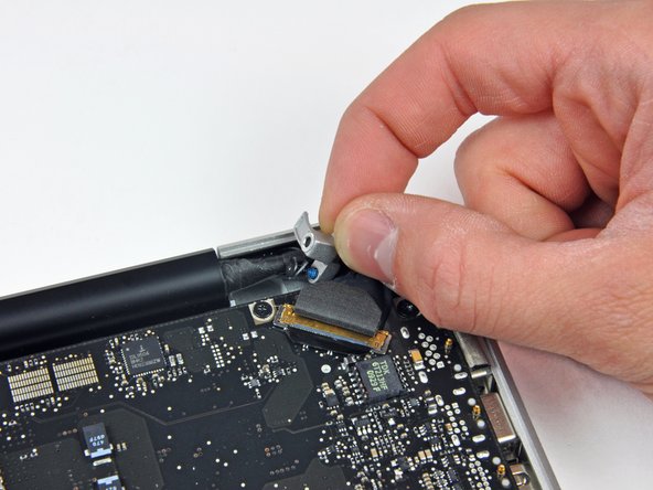
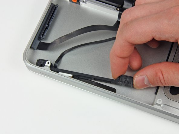
    • Apple sticks a small strip of clear plastic with adhesive applied to one side to the logic board behind the camera cable connector to keep it in its socket. When moving it out of the way, be sure not to break any surface-mount components off the logic board.

    • Hold the end of the cable retainer down with one finger while you use the tip of a spudger to slightly lift the other end and rotate it away from the camera cable connector.

  12. 这个步骤还没有翻译 帮忙翻译一下

    : 步骤 12 中的图像 1,1
    • Disconnect the camera cable by pulling the male end straight away from its socket.

    • Pull the connector parallel to the face of the logic board, not straight up.

  13. 这个步骤还没有翻译 帮忙翻译一下

    : 步骤 13 中的图像 1,1
    • Use the flat end of a spudger to pry the optical drive cable connector up off the logic board.

  14. 这个步骤还没有翻译 帮忙翻译一下

    : 步骤 14 中的图像 1,1
    • Using the flat end of a spudger, pry the subwoofer connector straight up off the logic board.

  15. 这个步骤还没有翻译 帮忙翻译一下

    : 步骤 15 中的图像 1,1
    • Use the flat end of a spudger to pry the hard drive/IR sensor cable connector up off the logic board.

  16. 这个步骤还没有翻译 帮忙翻译一下

    : 步骤 16 中的图像 1,2 : 步骤 16 中的图像 2,2
    • Remove the two 1.5 mm Phillips screws securing the cable cover to the logic board.

    • Lift the cable cover out of the upper case.

  17. 这个步骤还没有翻译 帮忙翻译一下

    : 步骤 17 中的图像 1,1
    • Use a spudger to pry the trackpad flex ribbon cable connector up off the logic board.

  18. 这个步骤还没有翻译 帮忙翻译一下

    : 步骤 18 中的图像 1,1
    • Using the tip of a spudger, flip up the keyboard ribbon cable retaining flap.

    • Pull the keyboard ribbon cable straight out of its socket.

  19. 这个步骤还没有翻译 帮忙翻译一下

    : 步骤 19 中的图像 1,1
    • Use a spudger to pry the battery indicator ribbon cable connector up off the logic board.

  20. 这个步骤还没有翻译 帮忙翻译一下

    : 步骤 20 中的图像 1,2 : 步骤 20 中的图像 2,2
    • Remove the single 7 mm Phillips screw securing the display data cable retainer to the upper case.

    • This screw may remain captive in the display data cable ground loop. If replacing the display, be sure to transfer this screw to the new unit.

    • Remove the display data cable retainer from the upper case.

  21. 这个步骤还没有翻译 帮忙翻译一下

    : 步骤 21 中的图像 1,2 : 步骤 21 中的图像 2,2
    • Grab the plastic pull tab secured to the display data cable lock and rotate it toward the DC-in side of the computer.

    • Pull the display data cable connector straight away from its socket.

    • Make sure to pull the connector parallel to the face of the logic board, not straight up from its socket.

  22. 这个步骤还没有翻译 帮忙翻译一下

    : 步骤 22 中的图像 1,2 : 步骤 22 中的图像 2,2
    • Using the tip of a spudger, flip up the keyboard backlight ribbon cable retaining flap.

    • Pull the keyboard backlight ribbon cable straight out of its socket.

  23. 这个步骤还没有翻译 帮忙翻译一下

    : 步骤 23 中的图像 1,1
    • Remove the following screws:

    • Eight 3.5 mm T6 Torx screws securing the logic board to the upper case.

    • Two T6 Torx screws securing the DC-In board to the upper case.

    • Do not remove the logic board yet! There are connectors attached to the underside of the logic board that must first be disconnected.

  24. 这个步骤还没有翻译 帮忙翻译一下

    : 步骤 24 中的图像 1,1
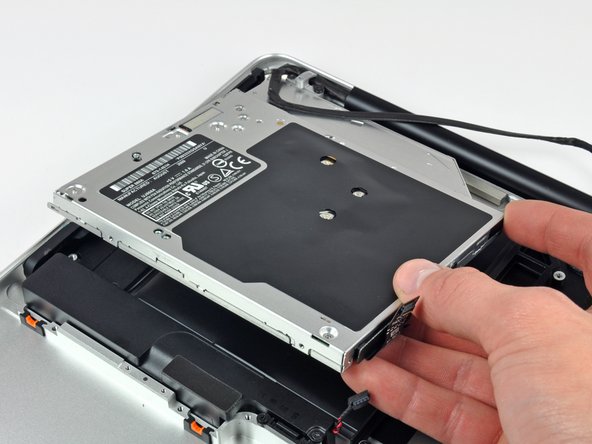
    • Carefully lift the logic board assembly from the left side and work it out of the upper case, minding the port side that may get caught during removal.

    • Do not entirely remove the logic board yet!

    • Ensure that the logic board is free from all connections to the upper case (except the battery connector) before proceeding.

  25. 这个步骤还没有翻译 帮忙翻译一下

    : 步骤 25 中的图像 1,2 : 步骤 25 中的图像 2,2
    • Lift the logic board enough to gain clearance and use a spudger to pry the microphone up off the upper case.

    • Slide the logic board away from the port openings and lift the assembly out of the upper case.

    • Before reinstalling the logic board, it is easiest to press the microphone down into its housing in the left speaker to keep it in place.

  26. 这个步骤还没有翻译 帮忙翻译一下

    : 步骤 26 中的图像 1,2 : 步骤 26 中的图像 2,2
    • Remove the two Phillips screws securing the hard drive bracket to the upper case.

    • These screws are captive to the hard drive bracket.

    • Remove the hard drive bracket from the upper case.

  27. 这个步骤还没有翻译 帮忙翻译一下

    : 步骤 27 中的图像 1,1
    • Lift the hard drive out of the upper case by its plastic pull tab, minding the cable attaching it to the computer.

  28. 这个步骤还没有翻译 帮忙翻译一下

    : 步骤 28 中的图像 1,2 : 步骤 28 中的图像 2,2
    • Remove the hard drive from its cable by pulling the cable connector straight away from the drive.

  29. 这个步骤还没有翻译 帮忙翻译一下

    : 步骤 29 中的图像 1,3 : 步骤 29 中的图像 2,3 : 步骤 29 中的图像 3,3
    • Remove the following four screws securing the hard drive and IR sensor cable to the upper case:

    • Two 1.5 mm Phillips screws.

    • Two 4 mm Phillips screws.

    • Slide the hard drive and IR sensor bracket away from the edge of the upper case.

    • Carefully peel the hard drive and IR sensor cable from the upper case.

    • Remove the hard drive/IR sensor cable from the upper case and set it aside.

  30. 这个步骤还没有翻译 帮忙翻译一下

    : 步骤 30 中的图像 1,2 : 步骤 30 中的图像 2,2
    • Disconnect the Bluetooth cable by pulling the male end straight away from its socket.

    • Use the flat end of a spudger to carefully pry the AirPort antenna off its socket on the AirPort card.

    • Pull the connector parallel to the face of the logic board, not straight up.

  31. 这个步骤还没有翻译 帮忙翻译一下

    : 步骤 31 中的图像 1,2 : 步骤 31 中的图像 2,2
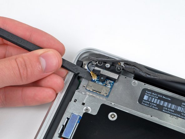
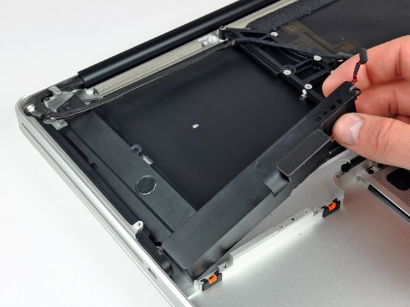
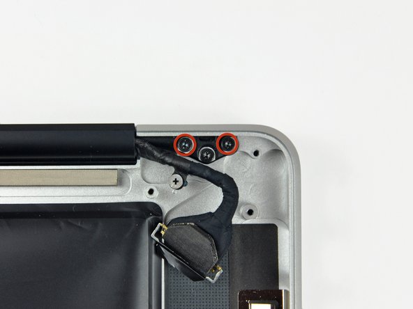
    • Remove the two 8 mm Phillips screws securing the Bluetooth/camera cable retainer to the upper case.

    • One of the screws may remain captive in the Bluetooth/camera cable ground loop. If replacing the display, be sure to transfer this screw to the new unit.

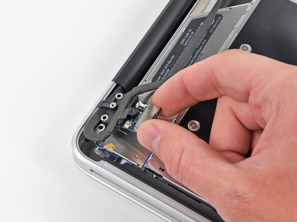
    • Lift the AirPort board/cable retainer assembly out of the upper case.

  32. 这个步骤还没有翻译 帮忙翻译一下

    : 步骤 32 中的图像 1,2 : 步骤 32 中的图像 2,2
    • Remove three 3.5 mm Phillips screws securing the optical drive to the upper case.

    • Lift the optical drive from its left edge and pull it out of the computer.

  33. 这个步骤还没有翻译 帮忙翻译一下

    : 步骤 33 中的图像 1,2 : 步骤 33 中的图像 2,2
    • Remove the following four screws securing the subwoofer and right speaker to the upper case:

    • Two 3.2 mm Phillips screws.

    • One 2.6 mm Phillips screw.

    • One 5 mm Phillips screw.

    • Lift the subwoofer and right speaker assembly out of the upper case.

  34. 这个步骤还没有翻译 帮忙翻译一下

    : 步骤 34 中的图像 1,2 : 步骤 34 中的图像 2,2
    • Remove two outer 6 mm Torx screws securing each side of the display to the upper case (4 screws total).

    • We intentionally have you leave one screw in each hinge to aid in the following steps.

  35. 这个步骤还没有翻译 帮忙翻译一下

    : 步骤 35 中的图像 1,1
    • Open your MacBook Pro so the display is perpendicular to the upper case.

    • Place your opened MacBook Pro on a table as pictured.

    • While holding the display and upper case together with your other hand, remove the 6 mm Torx screw from the lower display bracket.

  36. 这个步骤还没有翻译 帮忙翻译一下

    : 步骤 36 中的图像 1,1
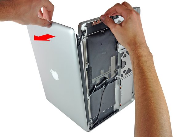
    • Be sure to hold the display and upper case together with your other hand. Failure to do so may cause the freed display/upper case to fall, potentially damaging each component.

    • Remove the last remaining 6 mm Torx screw securing the display to the upper case.

  37. 这个步骤还没有翻译 帮忙翻译一下

    : 步骤 37 中的图像 1,3 : 步骤 37 中的图像 2,3 : 步骤 37 中的图像 3,3
    • Grab the upper case with your right hand and rotate it slightly toward the top of the display so the upper display bracket clears the edge of the upper case.

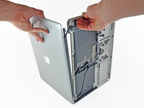
    • Rotate the display slightly away from the upper case.

    • Lift the display away from the upper case, minding any brackets or cables that may get caught.

终点

3等其他人完成本指南。

0条评论

添加评论

浏览统计数据:

过去 24 小时: 1

过去 7 天: 13

过去 30 天: 19

总计 10,213