跳转到主内容
加入维修社区 - 创建账户

此翻译由机器生成,尚未经过人工审核。 会说这种语言吗? 查看评论

FAKIR 1800 ECO

你所需要的

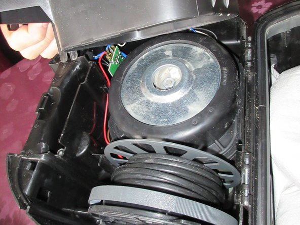
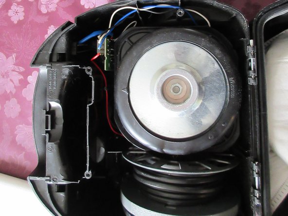
    1. FAKIR 1800 ECO, Fakir 1800 Eco 双向可控硅(晶闸管): 步骤 1 中的图像 1,3 FAKIR 1800 ECO, Fakir 1800 Eco 双向可控硅(晶闸管): 步骤 1 中的图像 2,3 FAKIR 1800 ECO, Fakir 1800 Eco 双向可控硅(晶闸管): 步骤 1 中的图像 3,3
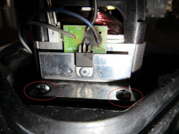
      • 首先拔下插头并卷好线缆。拔下真空软管。打开机器。

      • 共有四颗 PH2 螺丝。

      • 这些螺丝长度相同。

      询问修复机器人
      添加评论

    2. FAKIR 1800 ECO: 步骤 2 中的图像 1,3 FAKIR 1800 ECO: 步骤 2 中的图像 2,3 FAKIR 1800 ECO: 步骤 2 中的图像 3,3
      • 螺丝细节

      • 用力拉,它就会脱开

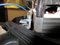
      • 看,这里有一个卡扣,另一侧还有第二个卡扣

      询问修复机器人

      添加评论

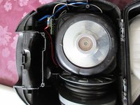
    3. FAKIR 1800 ECO: 步骤 3 中的图像 1,3 FAKIR 1800 ECO: 步骤 3 中的图像 2,3 FAKIR 1800 ECO: 步骤 3 中的图像 3,3
      • 看,那是步骤 2 中的第二个卡扣。

      • 拉。

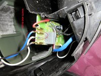
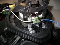
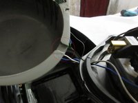
      • 打开。看,你需要拆掉那里的白色线缆和蓝色线缆。

      • 蓝色线缆和白色线缆的插头尺寸不同。它们只能对应装回正确的位置。;)

      询问修复机器人
      添加评论

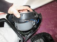
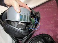
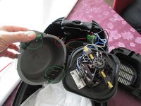
    4. FAKIR 1800 ECO: 步骤 4 中的图像 1,3 FAKIR 1800 ECO: 步骤 4 中的图像 2,3 FAKIR 1800 ECO: 步骤 4 中的图像 3,3
      • 拉出涡轮,它被橡胶外壳卡住了。直接用力拉。

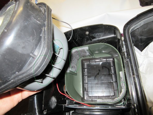
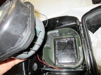
      • 然后再次用力拉出灰色塑料件。查看过滤器,在重新组装时它们必须彼此相对!!!已在绿色圆圈中标记。

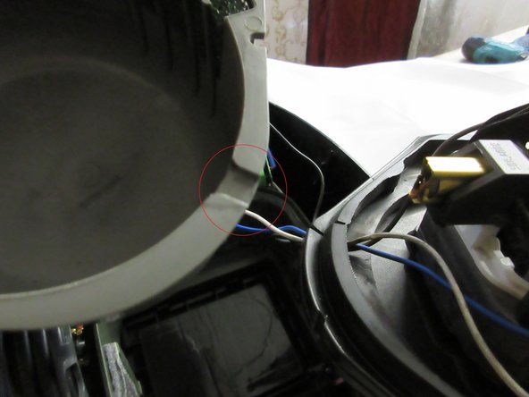
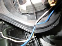
      • 看红色圆圈处,有一个凹槽,那是白色线缆、蓝色线缆和黑色线缆穿过外壳的地方。

      询问修复机器人
      添加评论

    5. FAKIR 1800 ECO: 步骤 5 中的图像 1,3 FAKIR 1800 ECO: 步骤 5 中的图像 2,3 FAKIR 1800 ECO: 步骤 5 中的图像 3,3
      • 白色线缆与蓝色线缆细节。插头带有一个小型弹簧固定件,必须按压固定件后再拔下!!

      • 插头尺寸不同。

      • 拔下电机上较短的黑色线缆。该插头同样带有一个需要按压的弹簧,按压后即可拔下黑色线缆。

      询问修复机器人
      添加评论

    6. FAKIR 1800 ECO: 步骤 6 中的图像 1,3 FAKIR 1800 ECO: 步骤 6 中的图像 2,3 FAKIR 1800 ECO: 步骤 6 中的图像 3,3
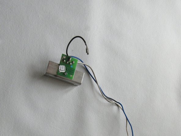
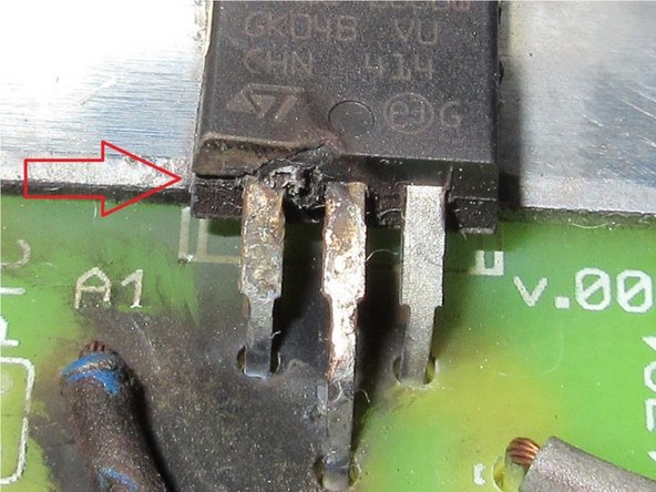
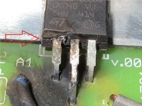
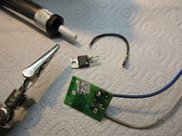
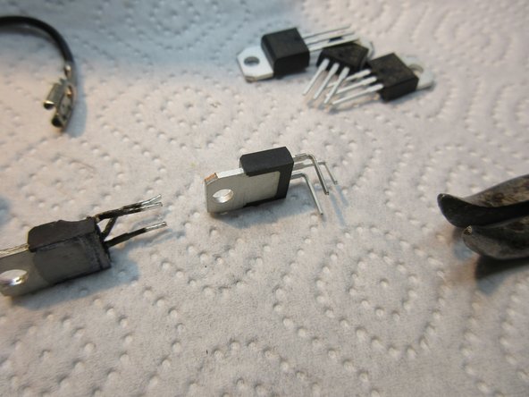
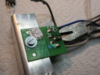
      • 这就是坏掉的烧毁双向可控硅(TRIAC),连带着线缆和铝制散热片。

      • 这个部件在外壳处损坏,请看红色箭头。引脚在外壳处直接弯曲了,说明这次损坏是在安装这个双向可控硅时造成的!太糟糕了。:( 电流让它炸开了,并造成了彻底损毁。

      • 线缆看起来没问题,电路板也是好的。看起来烧焦了,但这只是黑烟熏黑的。

      • 现在我们需要把那个零件钻出来……

      询问修复机器人

      添加评论

    7. FAKIR 1800 ECO: 步骤 7 中的图像 1,3 FAKIR 1800 ECO: 步骤 7 中的图像 2,3 FAKIR 1800 ECO: 步骤 7 中的图像 3,3
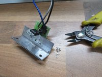
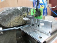
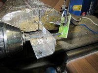
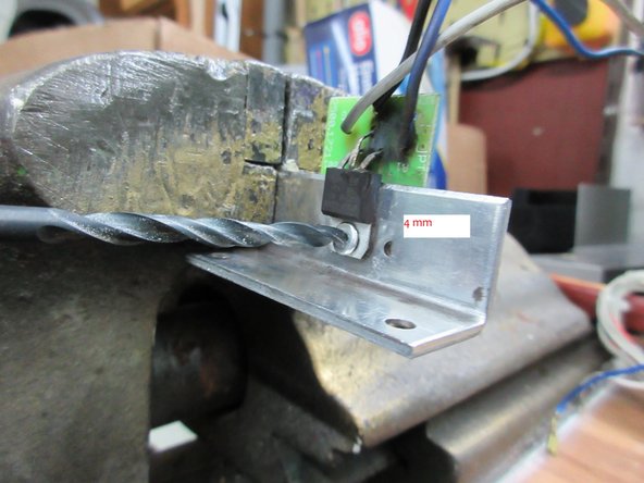
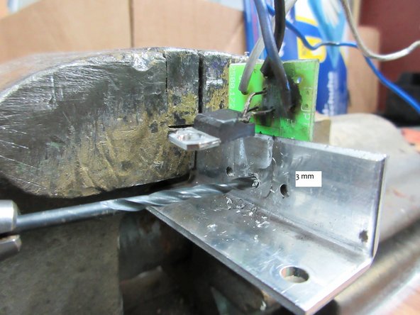
      • 首先,使用 4 mm 的钻头。

      • 小心地制作该部件。

      询问修复机器人
      添加评论

    8. FAKIR 1800 ECO: 步骤 8 中的图像 1,3 FAKIR 1800 ECO: 步骤 8 中的图像 2,3 FAKIR 1800 ECO: 步骤 8 中的图像 3,3
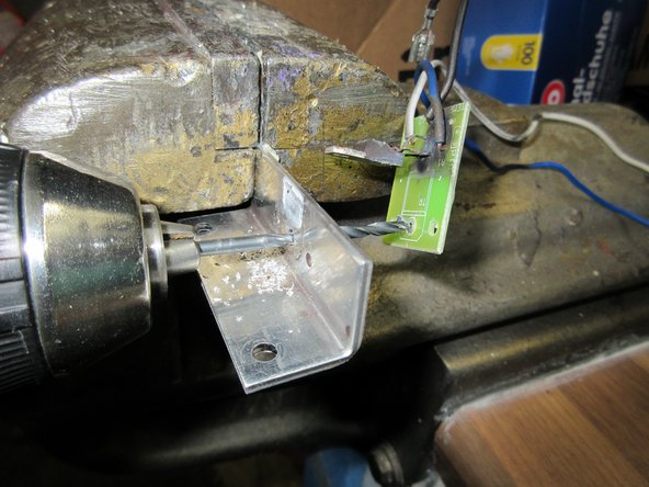
      • 然后向上拉起损坏的 TRIAC。

      • 接着使用 3 mm 钻头钻孔,穿透电路板。

      • 大功告成,所有部件都拆解好了。:)

      询问修复机器人
      添加评论

    9. FAKIR 1800 ECO: 步骤 9 中的图像 1,3 FAKIR 1800 ECO: 步骤 9 中的图像 2,3 FAKIR 1800 ECO: 步骤 9 中的图像 3,3
      在这个步骤中使用的工具:
      Desoldering Pump
      $3.99
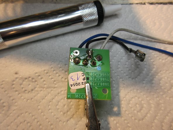
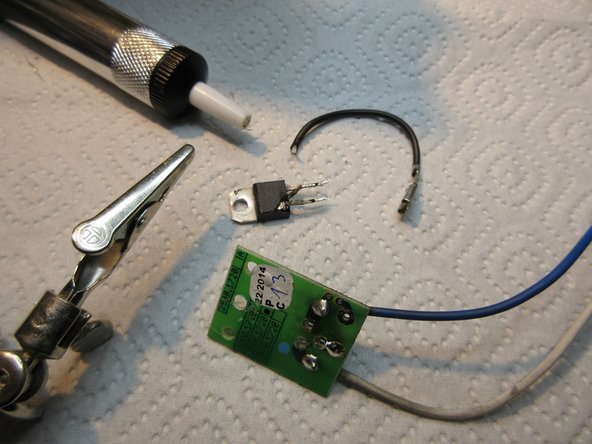
      • 现在进行脱焊。电路板上有两个孔,正好可以安装在铝制散热器上。

      • 使用 吸锡泵 处理起来没有问题。

      询问修复机器人

      添加评论

    10. FAKIR 1800 ECO: 步骤 10 中的图像 1,3 FAKIR 1800 ECO: 步骤 10 中的图像 2,3 FAKIR 1800 ECO: 步骤 10 中的图像 3,3
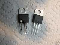
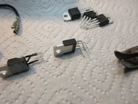
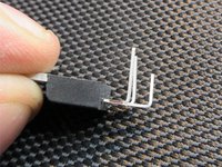
      • 更换新零件。

      • 请按照图片中的步骤操作,很抱歉我无法详细解释。只需按照图片所示进行即可。

      询问修复机器人

      添加评论

    11. FAKIR 1800 ECO: 步骤 11 中的图像 1,2 FAKIR 1800 ECO: 步骤 11 中的图像 2,2
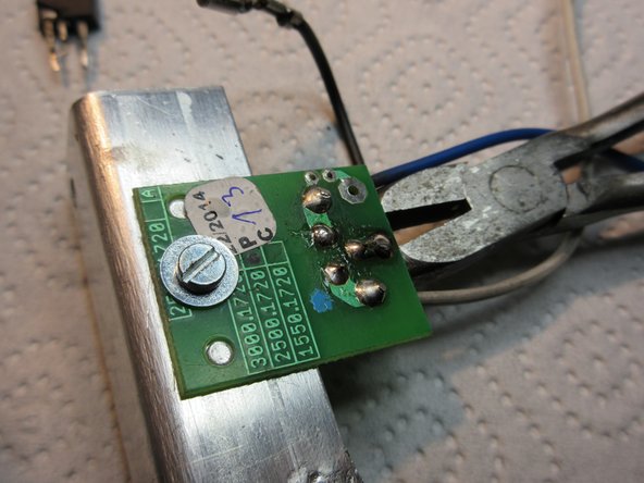
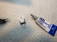
      • 取少量导热膏。只需极少量即可。

      • 取 M3 螺丝和 M3 垫圈,将其安装到铝制部件上。

      • 在机械应力(安装)完成后,焊接新部件。

      询问修复机器人

      添加评论

    12. FAKIR 1800 ECO: 步骤 12 中的图像 1,1
      • 我做了一个散热升级,你不需要跟着做,因为这只是一个 DIY 改装,其实没有必要。XD

      询问修复机器人

      添加评论

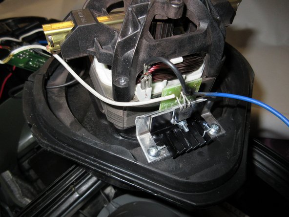
    13. FAKIR 1800 ECO: 步骤 13 中的图像 1,3 FAKIR 1800 ECO: 步骤 13 中的图像 2,3 FAKIR 1800 ECO: 步骤 13 中的图像 3,3
      • 现在进行重新组装

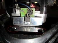
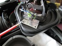
      • 将其装回,然后你需要两颗短的 PH2 螺丝。

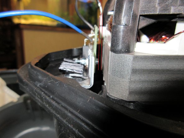
      • 注意零件之间的间距,如第三张图片所示,我用两条红线标记了出来。

      询问修复机器人

      添加评论

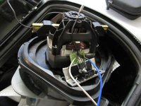
    14. FAKIR 1800 ECO: 步骤 14 中的图像 1,3 FAKIR 1800 ECO: 步骤 14 中的图像 2,3 FAKIR 1800 ECO: 步骤 14 中的图像 3,3
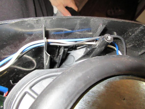
      • 然后将白色和蓝色线缆放好,此处还有第二根较长的黑色线缆。

      • 注意观察凹槽,必须确保安装到位。

      • 请确保滤网安装妥当。

      询问修复机器人

      添加评论

    15. FAKIR 1800 ECO: 步骤 15 中的图像 1,1
      • 外壳中的过滤器细节

      询问修复机器人

      添加评论

    16. FAKIR 1800 ECO: 步骤 16 中的图像 1,3 FAKIR 1800 ECO: 步骤 16 中的图像 2,3 FAKIR 1800 ECO: 步骤 16 中的图像 3,3
      • 线缆细节。

      • 有用于固定线缆的凹槽。

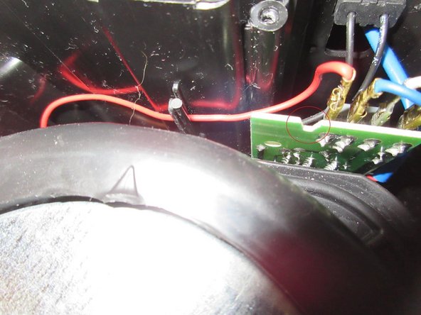
      • 看,第三张图片中板子上有一个大凹槽。红色圆圈处。当你合上该部件时,外壳的一个卡扣会卡入这个凹槽中。查看步骤 1 到 4,了解需要注意卡扣、凹槽和夹子的位置。

      询问修复机器人

      添加评论

    17. FAKIR 1800 ECO: 步骤 17 中的图像 1,1
      • 只有当所有部件能够完美贴合,确保所有的卡扣、凹槽和夹扣都已对齐,并且你用力按压外壳后,你才能小心地拧入那 4 颗较长的螺丝。

      • 测试一下,功能正常,搞定,现在来杯野格吧。

      • :D

      • 只说了几句,抱歉,我的英语不太好,但希望这些图片能对你有所帮助。

      询问修复机器人

      添加评论

结论

按照相反的顺序执行操作步骤,即可将设备重新组装起来。

取消:我没有完成这个指南。

4等其他人完成本指南。

Schwarzstein

于07/15/13注册

2,972 声望

创作了13篇指南

5指南评论

Well, my child played with that Vacuum-cleaner and it overheated.

So I had to do this repairmanual for you.

Do not let play children with Machines. ;)

Schwarzstein - 回复 分享

Just some comments for English speakers. I'm not dealing with spelling or awkward phrasing - I think it's clear emough. But for those that aren't sure on certain words, maybe this will help.

First tool listed is a #2 Philips-head screwdriver. So when you see PH2 screws, use your phillips screwdriver (also known as a cross screwdriver in some parts of the English-speaking world).

Step 2, middle bullet - "Pull, it knacks" literally would be cracks, which might sound negative. So "Pull, it does separate."

Step 4 (and elsewhere): turbine or motor.

Step 6, 1st bullet (& see Step 9 and elsewhere for variations) - (aluminium-)cooling or cooler = (aluminum) heat sink. [Americans don't use the 2nd i of aluminium.]

Step 6 (and elsewhere), 3rd bullet: platine = printed circuit board (I'll always refer to it as the PCB).

Part 2 of notes comes in my next comment --

J Stuart - 回复 分享

Part 2 of notes here --

Step 6, 2nd bullet [I know, out of order, but I wanted to use PCB, so translated it first] - Instead of translating it "The pins are bent directly at the housing, so this destruction occured at the montage of the triac !" I would've said "The pins are bent to go into the PCB, and the destructive forces inside the triac caused the assembly ("montage") to burst open at the other end of the pins, where they enter the triac housing!"

Steps 7-8 - there is a rivet that goes through the triack, then through the heat sink, then through the PCB. For getting the rivet out, you drill with a 4mm drill bit through the rivet head, through the triac mount, and lift the triac out of the way, then continue very carefully through the heat sink. Now the PCB can be removed from the heat sink. Then switch to a 3mm bit and drill the remnants of the rivet out of the PCB.

Part 3 coming up --

J Stuart - 回复 分享

Part 3 of 3 here

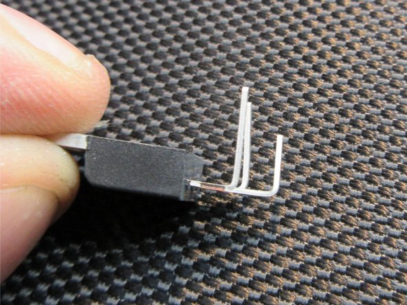
Step 10 - "follow the steps like on the pictures, i can't explain it, sorry. Like on the pictures, you can see, do it too" becomes "Follow the pictures in steps 4-10, especially step 6 and step 10. Pins 1 and 3 get bent closer to the triac, pin 2 (the middle pin) gets bent further out ('longer') from the triac, to fit the wholes in the PCB.

Step 11, 1st bullet - use less thermal grease/compund than is shown in the picture of step 11. He said "little" and that was correct.

Step 11, 2nd bullet - Instead of riveting (if you aren't good at it you might break the PCB), he replaces it with a bolt, washer, and nut. Tighten it - but not so much you break the PCB.

Starting Step 13, you're reassembling. His CONCLUSION at the end says to do the steps in reverse order to finish - maybe he later added steps 13 to the end later and didn't remove that statement.

Step 17 Jägermeister = hunt master -- go hunting things to vacuum up?

J Stuart - 回复 分享

@Schwarzstein: würdest Du Dir zutrauen, unser Gerät zu reparieren? Wir haben das Miele S8340 EcoLine.

Luca - 回复 分享

添加评论

浏览统计数据:

过去 24 小时: 5

过去 7 天: 30

过去 30 天: 113

总计 6,622