简介
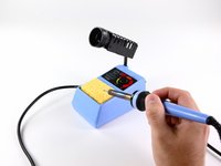
所以你刚刚购买了我们的一级焊接套件来练习通孔焊接。本指南将帮助你完成各个步骤,同时教你有关焊接、读取电阻数值以及元件极性的知识。很快,你就能够准备好为你的 iPod Nano 3rd Generation 更换电池了。
你所需要的
-
-
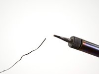
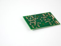
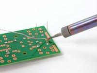
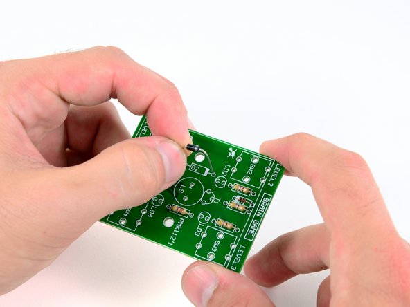
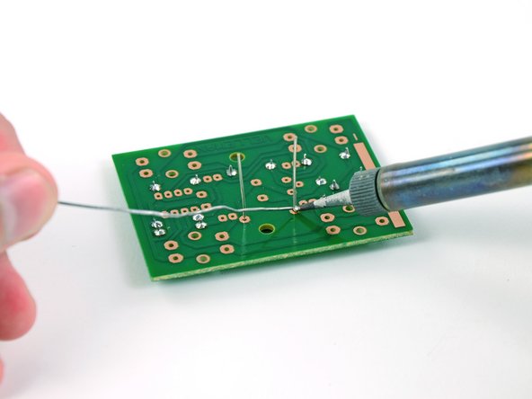
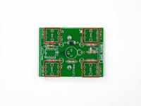
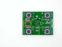
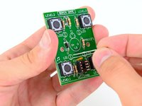
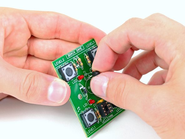
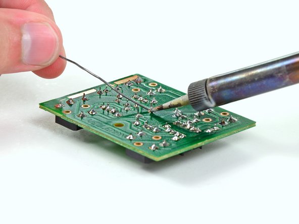
在深入進行腦力遊戲的組裝之前,我們應該先了解通孔焊接的程序。
-
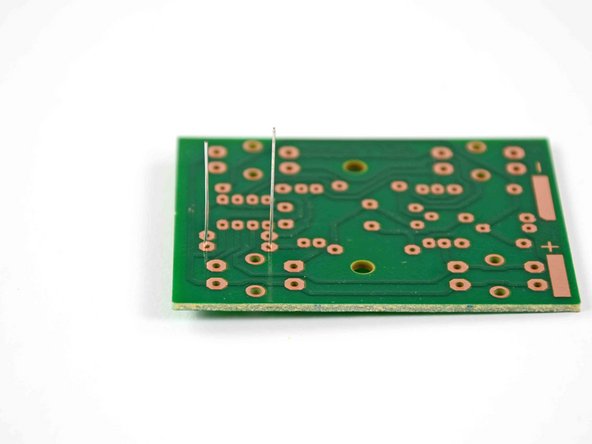
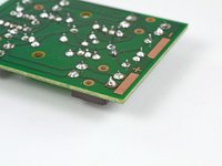
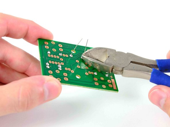
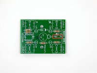
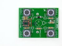
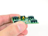
您可能會問,為什麼它被稱為通孔?您會注意到電路板上有許多孔,每個孔在板的底面上都有一條銅線。每個元件的引線都穿過這些孔(因此稱為通孔)並焊接到銅線上。
-
-
-
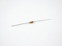
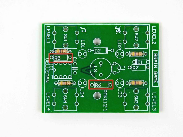
那么,什么是电阻器,我们为什么要关注它们呢?电阻器是电路中用来控制电流大小的元件。电阻器的电阻值(以欧姆Ω为单位)越大,允许通过的电流就越小。
-
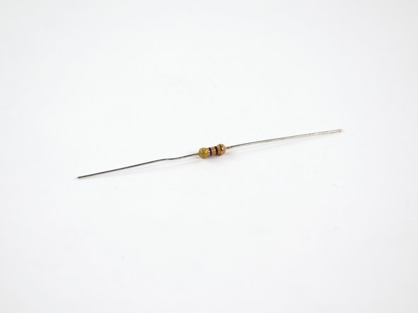
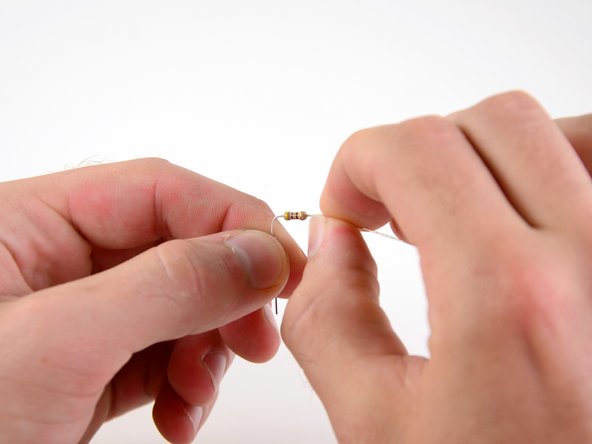
电阻上的色环是确定该电阻阻值的关键,这时电阻色码表就派上用场了。
-
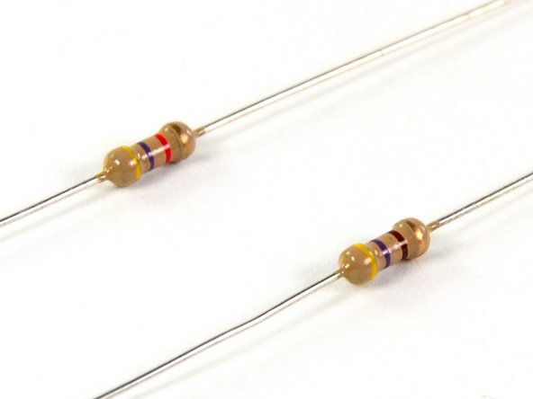
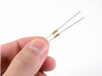
如果电阻上有四个色环,首先要找的是位于某一端膨胀处的红色、金色或银色色环,这些被称为误差环。由于我们的电阻带有金色环,可知其实际阻值在标称值的±5%范围内。
-
接下来需要确定电阻的标称值。从误差环的对侧开始,自左向右有三个色环:前两个色环分别对应一个数字(0-9),第三个色环是倍率环,对应10的特定次方。
-
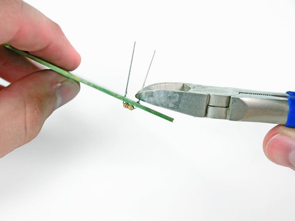
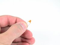
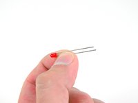
看顶部所示的电阻,其色环为黄、紫、红三色。查阅电阻色码表可知,这些颜色分别对应数字4、7和倍率100,因此该电阻的标称阻值为4700欧姆(Ω)。
-
-
-
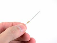
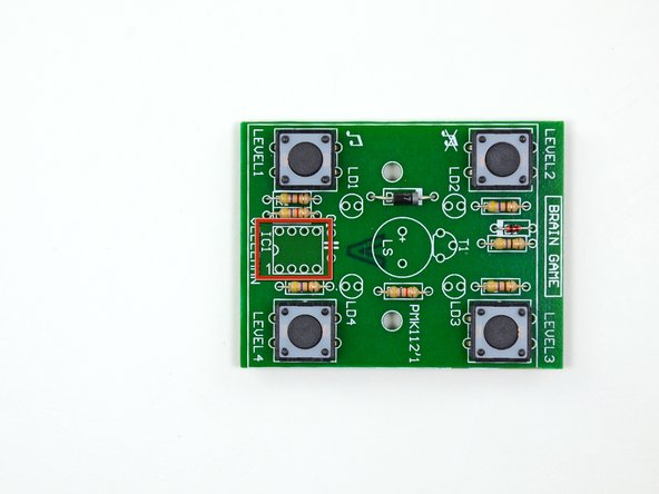
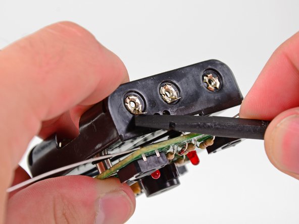
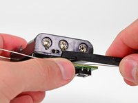
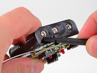
在您的元件套件中继续翻找,您会发现一些带有长引线的全新有趣元件。 (操作提示: 1. 这类元件可能是电解电容、电感或连接器 2. 长引线设计便于手工焊接和位置调整 3. 建议先用万用表检测
-
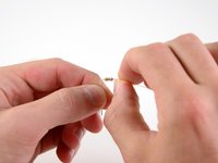
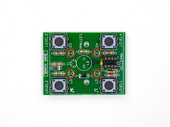
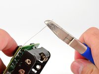
这些是二极管——电路中的"单向通行标志"。它们的作用是确保电流仅沿正向(从阳极到阴极)流动,同时阻止反向电流。 关键特性 1. 极性标识: - 阴极端通常有色环/凹槽标记(1N4148等玻璃管为黑色环,1N4007等塑封管为银色环) - 贴片二极管(如SS12)用阴极色带或三角形符号区分 2. 安装注意: - 必须正确识别PCB上的阳极(A)和阴极(K)标记 - 反接会导致电路失效,某些情况可能烧毁元件 3. 典型应用: - 整流交流电 - 防止电源反接 - 为感性负载(继电器/电机)提供续流路径 (若您找到的是发光二极管/LED,其长脚为阳极,但需串联限流电阻使用)
-
二极管极性安装要点 1. *性标识规则: - 阴极(K)端必定带有色环/条纹标记(通常为白色、黑色或银色) - 阳极(A)端无标记(平滑表面) 2. PCB安装验证: - 电路板上的二极管符号(|◁)中,三角形顶点指向阴极 - 丝印框的缺口侧或"K"标记对应阴极 3. 错误防范: - 通电前用万用表二极管档测试:正向导通电压约0.6V(硅管)/0.3V(锗管),反向显示"OL" - 反接时电源可能短路触发保护,某些场景会引发元件爆裂 (特殊类型提示:稳压二极管/齐纳二极管需反向偏置工作,但仍需按标记安装)
-
-
-
-
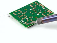
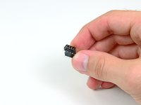
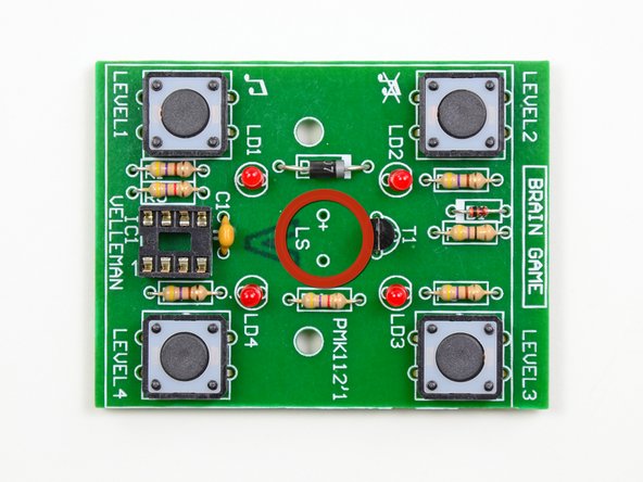
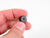
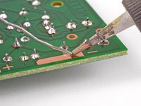
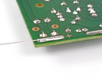
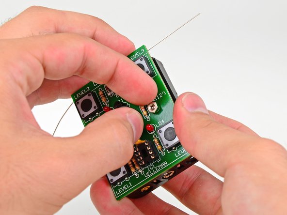
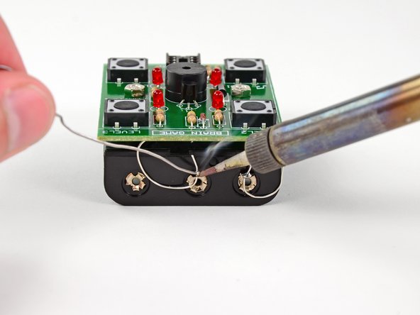
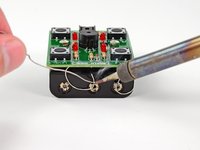
奖励!你以为自己只是学习通孔焊接,但这个套件还附带了一个表面贴装焊接的入门教程。表面贴装焊接通常用于将电池连接到某些设备的电路板上,例如 iPod。
-
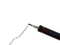
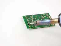
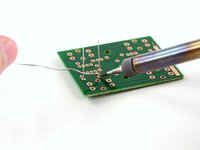
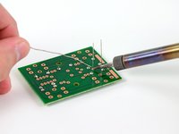
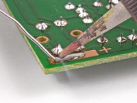
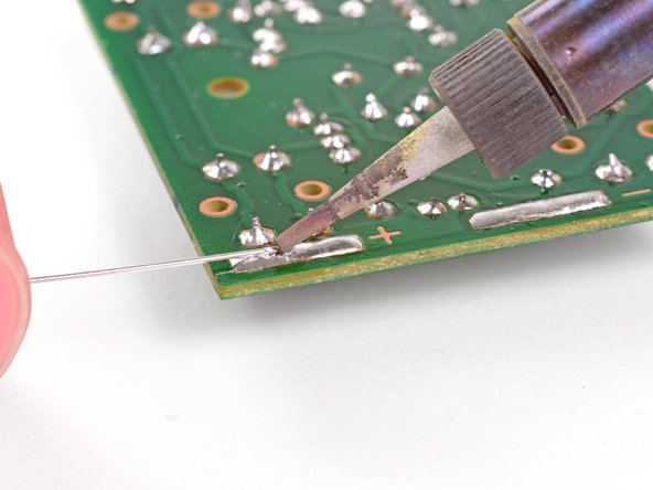
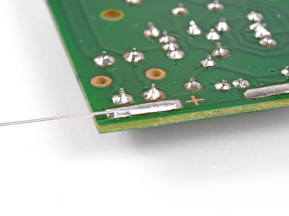
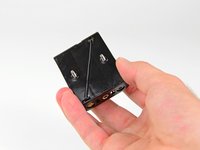
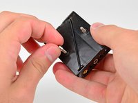
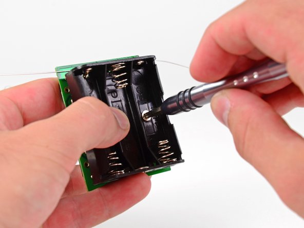
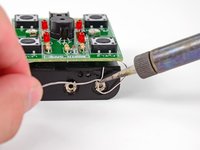
将焊接铁的尖端放在大的铜负极焊盘上。这将使热量传导通过焊盘,从而更容易焊接。
-
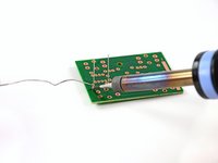
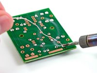
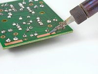
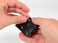
将焊锡接触焊接铁的尖端,并不断添加,直到在铜焊盘上形成光滑、凸起的焊锡圆顶。
-
-
-
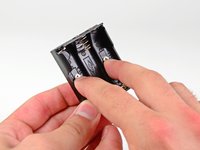
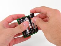
在电池仓中安装三节 AA 电池。
-
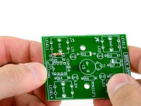
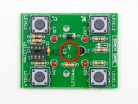
插入最后一节电池后,四个 LED 灯应开始顺时针闪烁。恭喜,你成功了!
-
要玩游戏,请按照以下说明操作:
-
取出一节电池。然后在按住 Level 2 按钮(无声音)或 Level 1 按钮(有声音)的同时重新插入电池。在电池插入几秒钟后松开按钮。游戏最终会自动关闭。要唤醒游戏进行游玩,按 Level 1 按钮可带声音游玩,或按 Level 2 按钮无声游玩。
-
当 LED 灯顺时针旋转闪烁时,按四个按钮中的一个来选择难度等级(按钮上方或下方印有等级)。
-
选择等级后,游戏开始。这是一个典型的类似 Simon Says 的记忆游戏。LED 灯会先闪烁一个灯,然后你必须按下相应按钮。接着它会闪烁两个灯,你必须按顺序点击这两个按钮。
-
游戏会一直进行,直到你搞错了模式或反应太慢。
-
玩得开心!别忘了在我们的故事区分享你的高分成绩。
-


109等其他人完成本指南。


10指南评论
Couldn't the CPU just be soldered in directly, instead of using the socket, or would this cause damage or something?
Yes you can, but it’s not a good idea. If you hold the soldering iron on the chip for too long, you might overheat it to the point of causing damage. This isn’t a problem for someone experienced with soldering, but it could be a problem for a beginner. Using a socket avoids the problem.
shamino -
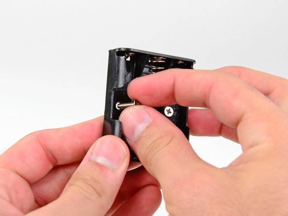
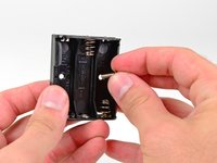
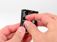
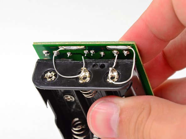
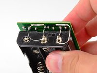
Thanks for a great tutorial, but apparently the design for the battery compartment has changed since this was made. It now comes with just one bendable lead on the top end and one on the bottom end of the compartment, which makes soldering to the battery compartment less straight forward. seems like it might be a manufacturing error. I got a replacement sent to me when I realized this, thinking it was a one-off, but the replacement has the same design. It's weird because even the (much less descriptive) guide that comes with the set shows 2 bendable leads on one end like yours.
jhubertful - 回复
I am having the same exact problem. My wife got this for me as an anniversary present. I am at the part where you are supposed to do the soldering to the battery box. Needless to say, I am stuck. I am thinking I’m going to have to find a piece of wire with insulation on it that I can use in the place of the junk that is in the box for this connection to the positive terminal. It’s the only solution I can think of, anyway.
The kits as they come will not be able to have the two small bendable leads attach to the battery pack. In the guide it shows both leads attaching on the same side of the box but the kit has a battery box with the leads on opposite sides. I ditched the bendable leads entirely and just used some extra with I had to complete the connection. Not a huge problem if you have spare wire but annoying.