跳转到主内容
加入维修社区 - 创建账户

Casio CZ-1000 Power Switch Replacement

你所需要的

    1. Casio CZ-1000 Power Switch Replacement, Backplate: 步骤 1 中的图像 1,2 Casio CZ-1000 Power Switch Replacement, Backplate: 步骤 1 中的图像 2,2
      • Use a Phillips #1 screwdriver to remove the eleven 7.5 mm screws securing the back plate.

      询问修复机器人

      添加评论

    2. Casio CZ-1000 Power Switch Replacement: 步骤 2 中的图像 1,3 Casio CZ-1000 Power Switch Replacement: 步骤 2 中的图像 2,3 Casio CZ-1000 Power Switch Replacement: 步骤 2 中的图像 3,3
      • Using a Phillips #1 screwdriver, remove all 14 5.5 mm screws from the two motherboards.

      • These screws secure the motherboards to the keyboard assembly and the dial on the right side.

      询问修复机器人

      添加评论

    3. Casio CZ-1000 Power Switch Replacement: 步骤 3 中的图像 1,3 Casio CZ-1000 Power Switch Replacement: 步骤 3 中的图像 2,3 Casio CZ-1000 Power Switch Replacement: 步骤 3 中的图像 3,3
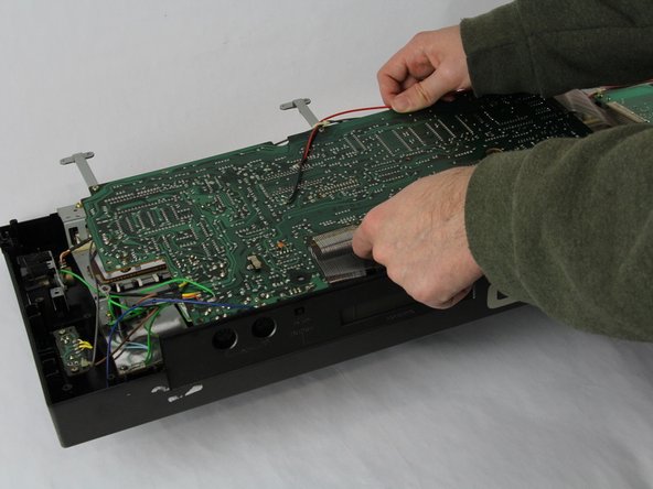
      • Carefully cut the zip tie located in the right-hand corner using a pair of scissors or wire cutters.

      • Be sure to avoid cutting any nearby wires or components.

      • Gently slide all the plugs out of their sockets.

      • This will prevent them from catching on anything or damaging the connectors as you lift.

      询问修复机器人

      添加评论

    1. Casio CZ-1000 Power Switch Replacement, Power Switch: 步骤 4 中的图像 1,1
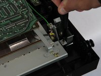
      • Remove the two 5.5 mm screws holding the power switch to the case using a Phillips #1 screwdriver.

      询问修复机器人

      添加评论

    2. Casio CZ-1000 Power Switch Replacement: 步骤 5 中的图像 1,3 Casio CZ-1000 Power Switch Replacement: 步骤 5 中的图像 2,3 Casio CZ-1000 Power Switch Replacement: 步骤 5 中的图像 3,3
      • Heat the soldering iron and use a desoldering braid or pump to remove the solder from the pins of the old switch.

      • Once the solder is removed, gently pull the old switch out of its place.

      • If the replacement switch doesn’t have pre-attached leads, you’ll need to solder wires to it. If it has leads, align them with the matching holes on the PCB where the old switch was connected.

      • Position the new switch in place, ensuring the leads align correctly with the pads on the PCB. Solder the leads securely, using just enough solder to create a strong connection without any excess that might cause shorts.

      询问修复机器人

      添加评论

结论

To reassemble your device, follow these instructions in reverse order.

取消:我没有完成这个指南。

Luke Farmer

于11/05/24注册

235 声望

撰写一个指南

团队

Cuesta, Team 60-3, Krynen Fall 2024 Cuesta, Team 60-3, Krynen Fall 2024 的会员

CUESTA-KRYNEN-F24S60G3

4 名成员

创作了10篇指南

0指南评论

添加评论

浏览统计数据:

过去 24 小时: 0

过去 7 天: 4

过去 30 天: 20

总计 317