跳转到主内容

当前版本的文档还未经巡查,您可以查看最新的已查核版本

你所需要的

  1. 这个步骤还没有翻译 帮忙翻译一下

    : 步骤 1 中的图像 1,1
    • Remove the wrist strap, if present.

    • Remove the lithium-ion battery.

  2. 这个步骤还没有翻译 帮忙翻译一下

    : 步骤 2 中的图像 1,3 : 步骤 2 中的图像 2,3 : 步骤 2 中的图像 3,3
    • Remove the two 4 mm Phillips #00 screws on the bottom of the camera.

    • Remove the screw next to the wrist strap attachment.

    • Pull up the “A/V OUT DIGITAL” cover and remove the screw above the USB port.

  3. 这个步骤还没有翻译 帮忙翻译一下

    : 步骤 3 中的图像 1,1
    • Carefully unhook the “A/V OUT DIGITAL” cover from the hinge.

  4. 这个步骤还没有翻译 帮忙翻译一下

    : 步骤 4 中的图像 1,2 : 步骤 4 中的图像 2,2
    • Pull the front cover from the camera by using gentle upward pressure.

  5. 这个步骤还没有翻译 帮忙翻译一下

    : 步骤 5 中的图像 1,2 : 步骤 5 中的图像 2,2
    • Remove the two Phillips #00 screws from the flat end of the camera.

    • Remove the black L-shaped side cover plate.

    • Remove the silver u-shaped retainer plate.

  6. 这个步骤还没有翻译 帮忙翻译一下

    : 步骤 6 中的图像 1,1
    • Slide the back casing off.

  7. 这个步骤还没有翻译 帮忙翻译一下

    : 步骤 7 中的图像 1,1
    • The first screw that needs to be removed is located on the bottom of the camera, on the left hand side.

    • Using a Phillips #00 screwdriver remove the 0.133in silver screw on the bottom left-hand side.

  8. 这个步骤还没有翻译 帮忙翻译一下

    : 步骤 8 中的图像 1,2 : 步骤 8 中的图像 2,2
    • The second screw that needs to be removed is located on the top of the camera.

    • Using the same Phillips head screwdriver, remove the last 0.133in silver screw.

    • This will detach a silver U-shaped piece that was holding LCD screen on. Remove the piece and put it to the side.

  9. 这个步骤还没有翻译 帮忙翻译一下

    : 步骤 9 中的图像 1,1
    • The LCD screen should now only be attached by the LCD data cable.

    • Lift the screen from the right side and use a small screwdriver or other small opening device to flip the black portion of the connector upward to unlock it.

    • Carefully slide the data cable out of the connector.

    • The LCD should still be connected by the backlight cable.

  10. 这个步骤还没有翻译 帮忙翻译一下

    : 步骤 10 中的图像 1,2 : 步骤 10 中的图像 2,2
    • To remove the backlight cable, use another small opening device to unlock the backlight cable.

    • Carefully slide out the backlight cable.

    • The LCD screen should now be fully detached from the camera body.

  11. 这个步骤还没有翻译 帮忙翻译一下

    : 步骤 11 中的图像 1,1
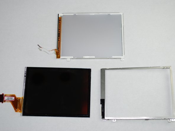
    • The LCD screen casing is connected by 4 claws located on the top and bottom on the left and right hand side.

    • Carefully disengage the claws by gently prying them off one by one.

    • Once the claws are disengaged, the back of the casing will still be connected to the front casing by the backlight cable.

    • Carefully peel the backlight cable off of the casing.

  12. 这个步骤还没有翻译 帮忙翻译一下

    : 步骤 12 中的图像 1,1
    • The LCD screen and housing should now be in three pieces:

    • LCD screen

    • LCD screen frame

    • LCD screen back housing

    • The LCD screen itself can now be removed and fixed/replaced.

  13. 这个步骤还没有翻译 帮忙翻译一下

    : 步骤 13 中的图像 1,2 : 步骤 13 中的图像 2,2
    • With the case and LCD screen removed, you are ready to remove the release button.

    • Begin by using the Philips #00 screwdriver to remove two silver 0.159in screws on the top and front of the camera.

  14. 这个步骤还没有翻译 帮忙翻译一下

    : 步骤 14 中的图像 1,1
    • The top plastic piece holding the release button should be held on only by a red-and-black wire connector to the logic board.

    • Remove the connector from the logic board and detach the release button housing from the camera.

  15. 这个步骤还没有翻译 帮忙翻译一下

    : 步骤 15 中的图像 1,2 : 步骤 15 中的图像 2,2
    • With the plastic housing for the release button removed from the camera, use the Philips #00 screwdriver to remove two silver 0.090in screws.

    • The release button can now be removed and fixed or replaced.

  16. 这个步骤还没有翻译 帮忙翻译一下

    : 步骤 16 中的图像 1,2 : 步骤 16 中的图像 2,2
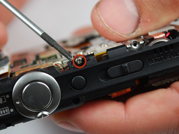
    • With the case, LCD screen, and release button housing removed, the logic board can be accessed and removed for replacement or repair.

    • Begin by using the Philips #00 screwdriver to remove two silver 0.080in screws on the left side of the metal housing plate (yellow circles).

    • Use the Philips #00 screwdriver to remove nine silver screws from the back and top of the camera (red circles).

    • You will have to lift the Function button and its wiring up from the pins holding it in place to access some of the screws.

  17. 这个步骤还没有翻译 帮忙翻译一下

    : 步骤 17 中的图像 1,1
    • The metal back plate can now be removed. All that is holding it on at this point are pins and wires connected to the logic board.

  18. 这个步骤还没有翻译 帮忙翻译一下

    : 步骤 18 中的图像 1,2 : 步骤 18 中的图像 2,2
    • Now, the wires connected to the logic board must be removed. Gently pull them out of their holders on the logic board.

    • Once the connectors are disconnected, the logic board can be removed for repair or replacement.

终点

Sam

于04/15/10注册

155 声望

创作了5篇指南

团队

Cal Poly, Team 10-45, Garner Spring 2010 Cal Poly, Team 10-45, Garner Spring 2010 的会员

CPSU-GARNER-S10S10G45

4 名成员

创作了6篇指南

0条评论

添加评论

浏览统计数据:

过去 24 小时: 1

过去 7 天: 10

过去 30 天: 10

总计 4,859