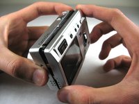
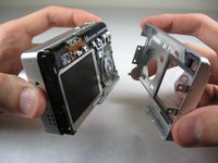
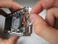
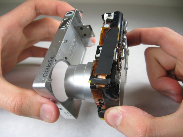
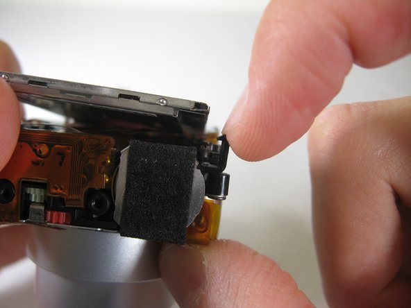
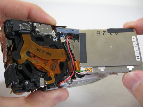
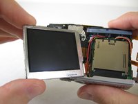
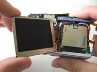
跳转到主内容
加入维修社区 - 创建账户

Accessing LCD Screen

你所需要的

  1. Accessing LCD Screen, Front and Back Cover: 步骤 1 中的图像 1,2 Accessing LCD Screen, Front and Back Cover: 步骤 1 中的图像 2,2
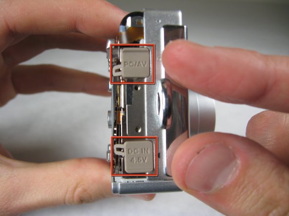
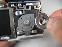
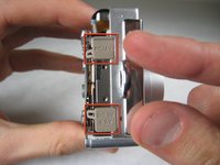
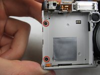
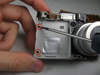
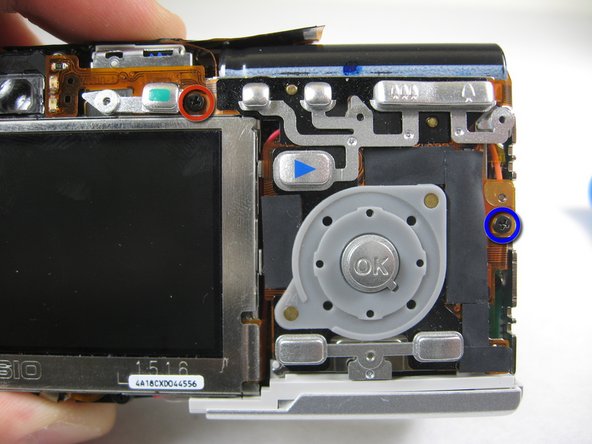
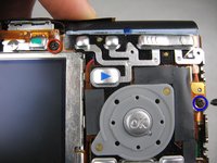
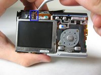
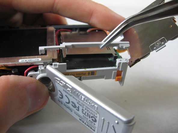
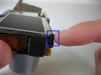
    • Remove the following screws:

    • Two silver 3.15mm Phillips #00 screws on the right side of the camera

    • Two silver 2.08mm Phillips #00 screws on the left side of the camera

    询问修复机器人
  2. Accessing LCD Screen: 步骤 2 中的图像 1,1
    • Remove the two indicated screws on the bottom of the camera:

    • The screw circled in red is a longer silver 3.15mm Phillips #00 screw

    • The screw circled in blue is a shorter silver 2.25mm Phillips #00 screw

    询问修复机器人
  3. Accessing LCD Screen: 步骤 3 中的图像 1,2 Accessing LCD Screen: 步骤 3 中的图像 2,2
    • Carefully pull the back of casing away from the front.

    询问修复机器人
  4. Accessing LCD Screen: 步骤 4 中的图像 1,3 Accessing LCD Screen: 步骤 4 中的图像 2,3 Accessing LCD Screen: 步骤 4 中的图像 3,3
    • After removing the back cover, several things must be removed.

    • Silver donut-shaped button will fall off. Place separately. Remove the plug covers on the right side of camera, labeled “PC/AV” and “DC IN 4.5V”.

    询问修复机器人
  5. Accessing LCD Screen: 步骤 5 中的图像 1,2 Accessing LCD Screen: 步骤 5 中的图像 2,2
    • To remove the front cover, gently hold the inside structure of the camera and slowly pull the front cover off.

    询问修复机器人
  6. Accessing LCD Screen, LCD: 步骤 6 中的图像 1,2 Accessing LCD Screen, LCD: 步骤 6 中的图像 2,2
    • On the front of the camera, in battery case, remove screws indicated:

    • Two black 2.05mm Phillips #00 screws

    询问修复机器人
  7. Accessing LCD Screen: 步骤 7 中的图像 1,2 Accessing LCD Screen: 步骤 7 中的图像 2,2
    • Flip the camera over to the backside and remove screws indicated:

    • The screw circled in red is a longer black 3.00mm Phillips #00 screw

    • The screw circled in red is a shorter black 2.00mm Phillips #00 screw

    询问修复机器人
  8. Accessing LCD Screen: 步骤 8 中的图像 1,1
    • Pull the cover plate off for the two power cord jacks.

    询问修复机器人
  9. Accessing LCD Screen: 步骤 9 中的图像 1,3 Accessing LCD Screen: 步骤 9 中的图像 2,3 Accessing LCD Screen: 步骤 9 中的图像 3,3
    • Cautiously and gently pull up the control board at the upper left corner, next to the viewfinder.

    询问修复机器人
  10. Accessing LCD Screen: 步骤 10 中的图像 1,1
    • Remove the orange tape on top of the SD cardholder.

    询问修复机器人
  11. Accessing LCD Screen: 步骤 11 中的图像 1,3 Accessing LCD Screen: 步骤 11 中的图像 2,3 Accessing LCD Screen: 步骤 11 中的图像 3,3
    • Open the battery cover and lift plastic piece off.

    询问修复机器人
  12. Accessing LCD Screen: 步骤 12 中的图像 1,1
    • Remove tape on left side of camera.

    询问修复机器人
  13. Accessing LCD Screen: 步骤 13 中的图像 1,1
    • Remove the indicated 2.40mm Phillips #00 screw to release top left LCD bracket.

    询问修复机器人
  14. Accessing LCD Screen: 步骤 14 中的图像 1,1
    • Remove top left LCD bracket.

    • This is a small piece, be careful not to lose it.

    询问修复机器人
  15. Accessing LCD Screen: 步骤 15 中的图像 1,2 Accessing LCD Screen: 步骤 15 中的图像 2,2
    • Push down bottom left LCD bracket to release the LCD from grip.

    询问修复机器人
  16. Accessing LCD Screen: 步骤 16 中的图像 1,1
    • Gently lift up LCD screen.

    询问修复机器人
  17. Accessing LCD Screen: 步骤 17 中的图像 1,3 Accessing LCD Screen: 步骤 17 中的图像 2,3 Accessing LCD Screen: 步骤 17 中的图像 3,3
    • Slowly pull LCD screen to the left to remove it from the other grips.

    • BEWARE: The LCD screen is attached to the logic board by two wires at the bottom.

    询问修复机器人
结论

To reassemble your device, follow these instructions in reverse order.

团队

Cal Poly, Team 4-29, Regan Winter 2011 Cal Poly, Team 4-29, Regan Winter 2011 的会员

CPSU-REGAN-W11S4G29

3 名成员

创作了10篇指南

0指南评论

添加评论

浏览统计数据:

过去 24 小时: 1

过去 7 天: 7

过去 30 天: 54

总计 1,462