跳转到主内容

电脑显示器维修。

501 个问题 查看全部

Won't turn on? LG - 34UM95-P UltraWide

Hi,

I was wondering if someone could give me some advice? I've never fixed anything electrical and would like to give it a shot.

My LG - 34UM95-P UltraWide monitor stopped working earlier this week. It won't power on, the white LED light near the joystick at the bottom of the screen is no longer turning on - neither is the monitor itself.

I've changed the fuse in the plug, but no joy.

I've had a look online and it's taken me down a bit of rabbit hole, I found one post that suggests the issue might be related to a EEPROM chip, perhaps it needs replacing or rebooting?

Wondering what tools would be useful to get to try and fix this monitor?

The monitor is in great condition for its age - purchased in 2014 - it's not been knocked about, I think something has just burned out (I have no idea).

It might be unrelated, but worth mentioning. I mainly used it with a MacBook Pro connected via Thunderbolt port. Never had any issues with this. In the last year or so a second PC laptop has occasionally been used with the monitor. Connecting via HDMI.

Sometimes the HDMI connection seemed a bit shaky, the monitor would make a white noise/static sound almost as if it was cutting out but only for a split second. Trying other HDMI ports on the monitor didn't seem to make a difference. Unplugging the HDMI lead and giving it a blow seemed to temporarily fix it. It was very random.

The monitor finally stopped working after the PC laptop performed a windows update.

The PC laptop wouldn't connect to the monitor and the image on the laptop was jumping all over the place. The monitor was blank, no power. Not sure if this is related?

Hope someone can offer some advice.

---

UPDATE #1

I've managed to open the back of the monitor. Images attached.

Block Image

Block Image


UPDATE #2 - Saturday, May 28, 2022

Test power adapter
I've tested the power adapter, multimeter showed 19v. So at least I know that's working as expected.
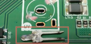

Test connector
I was unable to get the red probe deep enough into the connector, so I put it on the metal coming out of the connector, see red circle below. The black probe on a screw on the board, see black circle in the image below.

Block Image


The multimeter was set to resistance mode, and it beeped.

Block Image

I also tried the multimeter on two other resistance settings. First on a setting of 200, the reading was 01.0 then I changed the setting to 2k, the reading was .001

Test connector with power cable

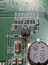
Set multimeter back to DC voltage mode, setting 20. Plugged power cable in and turned the power on. Black probe on the same screw as before, and red probe on L713 , gave me a solid reading of 19.20

Block Image


回答此问题 我也有这个问题

这是一个好问题吗?

得分 5
6条评论

@stephenmeehan check our AC adapter and make sure that it supplies the proper voltage

完成的

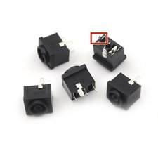
I have a similar issue, but it's the jack. I have to push the power supply plugged into the jack to the side to get it to work. Previously, the monitor would cut to black occasionally, and I wasn't sure what it was. Not I know. Issue is I see no places to find a replacement power jack. Just power supplies.

完成的

Is there anything else I can try?

完成的

@Jordan Thompson thanks for your comment, is the power jack not part of the power supply? Or do you mean the jack on the board? If so, It’s possible to replace this. See links in this post.

完成的

@stephenmeehan I'm having similar issue, I wonder if you manage to fix the issue, and which part was failing? Thanks!

完成的

显示更多的1条评论

添加一条评论

4个答案

最有帮助的答案

I fixed my monitor by reflashing firmwware on EEROM chip with dump file I found on on badcaps forum with CH341A programmer. As I have seen, a lot of these monitors have same issue, they just wont turn on. no sign of life. By just reflashing the EEROM chip problem can be solved. You even dont need to desolder the EEPROM chip, just hook up CH341a on to it and reflash it. Hope this helps.

这个答案有帮助吗?

得分 2

1条评论:

i think i have same problem. can you give more details? also have whatsap 0040751437612, placed one order for CH341A programmer

完成的

添加一条评论

Hi @stephenmeehan

I am almost certain that the issue is your power connector on the monitor. Especially because the white buzzing noise that you mentioned in your question.

These wider monitors usually operate on a 19V power supply with currents up to 3.5-4.5A. The connector is similar to a laptop DC IN connector with 2 inputs (V+ and GND) and usually they are soldered on the motherboard by 3 or 4 legs.

The static noise you heard was probably a leg come loose in that connector due to physical and/or electrical stress (almost 85Watts) at this tiny connector it may be burnt and/or broken and that is why the monitor is not turning on.

If you are able to take the monitor's back cover off and measure the input voltage, which should be 19V on the connector, you should see either 0V or a non stable voltage if you move the cable in the connector. If this is the source of the fault, you can desolder old connector and get a new one soldered in. If there was a short created by the loose connection at the power input, you may have a blown fuse on the motherboard as well.

Block Image

Block Image

Here's a link to a video on how to open the monitor:

https://www.youtube.com/watch?v=dlMphcRP...

Hope it helps!

这个答案有帮助吗?

得分 1

13条评论:

Thanks for the reply, that gives me something to try!

I think I'll be able to take the back off the monitor, thanks for sharing the video.

Can you recommend a device for measuring the input voltage? and what I'd need to remove the broken part and re-solder it?

完成的

You would need a digital multimeter first to do your measurements (iFixit sells them )

Then a soldering iron if the problem is the connector. Try to get a 60Watts or higher just because of the thremal mass of the board you need to desolder the connector from.

完成的

Thanks.

Thinking of getting this set on Amazon. What do you think? It’s 60w

Deal: Tabiger Soldering Iron Kit, Soldering Kit with LCD Digital Multimeter, 60W Soldering Iron with 5 Extra Tips, Stand, Desoldering Pump, Solder, Wire Stripper Cutter, Tweezers, Tape, Tool Bag https://smile.amazon.co.uk/dp/B08KVYD7DK...

With this soldering iron

0.8mm Solder Wire, Lead Free Soldering Wire with Rosin Core Solder Tin Wire for Electrical Soldering Electronic Components Repair and DIY(20g) https://smile.amazon.co.uk/dp/B09XJRP1R9...

Where can I get replacement connectors from? Do you know the name of them?

完成的

@honakrisi

Did a reverse image search. Looks like that part is called a DC jack SA300. Appears to be a standard part used in many monitors.

https://www.aliexpress.com/item/32961447...

完成的

Looks good. Bargain for that price.

With lead free solder I would buy some sort of flux to help the flow of solder.

Connector is similar to this:

https://www.ebay.co.uk/itm/255487224090?...

完成的

显示更多的8条评论

添加一条评论

@stephenmeehan For now just start using the LG flowchart for the no power situation. If you show 19V on C764 you know your jack is okay and you can move past it.

Block Image

Update (06/12/2022)

@stephenmeehan finally found the rest of it too. Check the IC's according to their required voltage. IC 703 and all the other IC's are pin 8 to be checked for the proper voltage. Looks like this beast (monitor:-) had issues with it's EEPROM. Looks like a lot of people(weirdly enough mostly Eastern European) flashed the EEPROM. Anyhow, this LG 34UM94 95 should help you getting your monitor back on the road :-)

这个答案有帮助吗?

得分 0

5条评论:

That’s really helpful, thanks for sharing that.

完成的

@stephenmeehan of course. Check the IC's as outlined. Let us know what you find

完成的

Like the OP I found this very helpful & informative. What's the reason that only IC703 has voltage checked on pin 7 and all others in pin 8?

完成的

@electricfish Good catch. Just rechecked the schematic and they are all pin 8. Answer has been edited to reflect this information. Thanks @electricfish

完成的

Thanks for confirming. I have very little knowledge of electronics, limited to just-enough self taught for hobby.

Sadly I now see there's a tiny charred pitz since.of pinhead on a pin 2/3 of IC703.

Is this thing a goner? Multilayer PCB and all, I think it's done for, right?

完成的

添加一条评论

See image attached - jpg

Block Image

这个答案有帮助吗?

得分 0

2条评论:

@electricfish yep, pretty gnarly. It is defininetly gone up in smoke ;-) The way IO would proceed is to desolder teh IC and clean teh board. Lets see if the solder pads are still good. If so, then you could actually try to fix it instead of replacing it. Once it is desolder and the board is clean, measure the voltage on pin 2, well in that case the solder pad where pin 2 connects to. You should have 19VDC on that. If you don't check on C724 for the voltage. Remember Black probe to ground and Red probe to test.

It really does not yet look dead yet. It's only dead if you say it is :-) Go for it. You got this. Let's give it a try to repair your board.

Repair is War on Entropy!

完成的

@electricfish here is the datasheet for the ICMP2315 Datasheet. The component is readily available at places like mouser.com digikey.com and many others. Cost around USD$3

完成的

添加一条评论

添加你的答案

Stephen Meehan 将永远感激不已
浏览统计数据:

过去 24 小时: 11

过去 7 天: 65

过去 30 天: 224

总计 5,957