简介
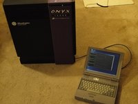
The Silicon Graphics Onyx was introduced in 1993 as SGI’s high-end graphics supercomputer. There are two different types of Onyx: the Onyx “rack”, which is about the size of a kitchen refrigerator, and the Onyx “deskside”, which is the miniature version you see here. The rack machine has more expansion slots for CPU and memory boards, and room for up to three graphics “pipelines”. The Onyx was succeeded by the Onyx2 in 1998.
The Onyx was available with the mips R4000, R8000, and R10000 processors; with 1, 2 or 4 CPUs per processor board. The various graphics options included RealityEngine2, which was an update to the original reality engine for the Crimson and PowerSeries machines. VTX was a cost-reduced RealityEngine2. InfiniteReality is the newest (1995) and most powerful graphics option for SGI Onyx, and it’s design lived on in newer machines such as the Onyx2 and Onyx3000. There are also a myriad of HIO and VME expansion options for networking, sound, advanced I/O for machine control or motion capturing, and “video” - which in the SGI universe is very different from “graphics”.
These machines were used by companies, universities, and governments for advanced CAD/CAE, FEA, fluid modeling, visualization, Hollywood special effects, and, of course, virtual reality. I purchased this particular Onyx "as-is" from a Boeing surplus auction in 2008. It required extensive repair to some of the graphics boards, and has had a few upgrades over the years. It is once again in perfect operational condition and a great machine to play quake 3 on, or to tinker around with Mathematica! Let’s take it completely to bits and see what’s inside!
你所需要的
-
-
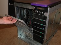
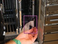
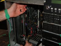
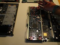
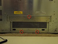
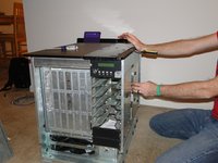
Begin by removing the back and side plastic skins.
-
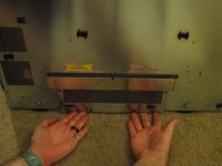
To remove the back and side skins, pull the bottom of the skin off, and then slide it down.
-
This Onyx is not outfitted with side skirt skins.
-
We will remove the top skin towards the end of the teardown, as it is only necessary to remove the skin when it is being replaced.
-
-
-
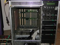
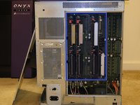
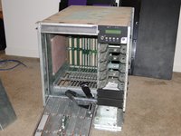
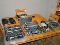
The bowels of the computer are now revealed to us!
-
The card cage is 9U VME size, which means that each board is about 14 inches square.
-
Memory Board (MC3, 32x64MB (2GB)
-
Processor Board (IP25, 4x MIPS R10000 @195Mhz)
-
I/O Board (SGI IO4)
-
Geometry Engine (4x GE12 SGI-proprietary ASICs)
-
Raster Manager (20x "quad core" image engines- 80 total, 16MB)
-
Display Generator (Two Graphic terminal DACs and video I/O
-
-
-
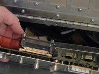
Remove the Infinite Reality frontplane by pulling it straight out. This circuit board connects the raster manager boards (up to 4) to the display generator.
-
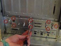
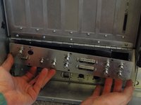
remove the SCSI and I/O bulkhead cables from the IO4 circuit board.
-
Pinch the side levers together and the connector will pop out.
-
Remove the graphics bulkhead cable from the display generator circuit board.
-
Two thumbscrews hold this cable in place. If these screws are stuck, a flat screwdriver can be used.
-
Hold these cables out of the way when removing circuit boards from the cage. They are fragile and can snag easily.
-
-
-
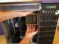
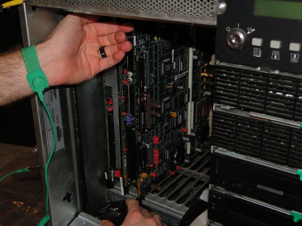
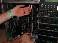
Remove circuit boards by pulling the top and bottom lever out simultaneously to disconnect the backplane connection.
-
When the card is disconnected from the backplane, slide the board out of the cage and store it in a safe place.
-
It is easier to remove a board next to an empty slot. If a board is sandwiched, especially the memory board (first slot) or display generator board (last slot), remove the adjacent board first.
-
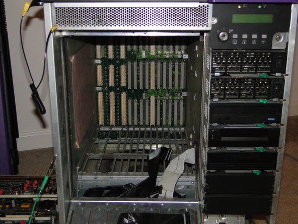
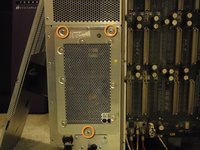
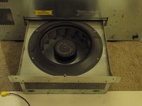
When all boards have been removed, admire the backplane and blower.
-
-
-
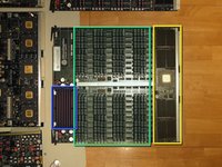
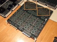
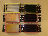
Let's take a closer look at all of that fancy circuitry we just pulled out. We'll start with the memory board, called an MC3.
-
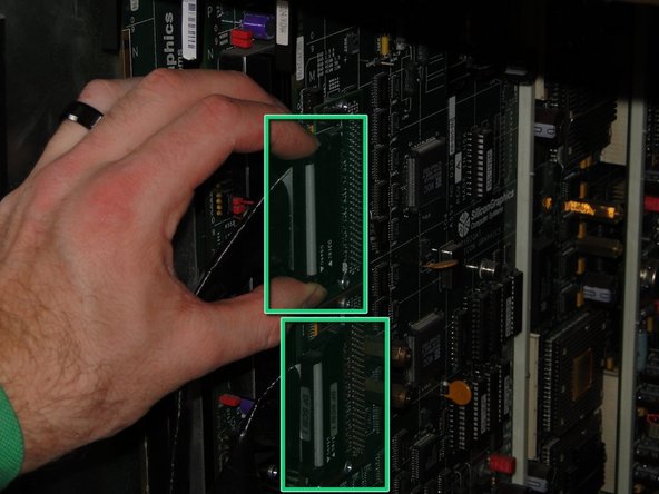
Memory is available in 16MB (pink stripe) and 64MB (purple/green stripe) simms. The simms are removed just like some old-fashioned PC memory from the early 90s: pull straight up on the white handle, and pray that nothing snaps!
-
Board Layout:
-
Everest powerchannel bus ASICs
-
Memory slots
-
48V to 5V DC-DC power converter
-
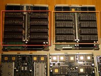
MC3 with 256MB memory (16x 16MB)
-
MC3 with 2GB memory (32x 64MB)
-
-
-
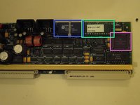
Remove these screws to separate the VCAM from the IO4 board
-
The VCAM interfaces the computer to the VME bus and graphics (PowerChannel bus)
-
PowerChannel controller ASICs and connection to VCAM board
-
HIO expansion connections for disk, graphics, audio, or other peripherals; and controller ASICs
-
Dallas real-time clock and battery backed NVRAM
-
WD33C95A SCSI controllers
-
VME interface and glue logic
-
SCSI riser boards: red is differential, green is single-ended. The system can be configured for two diff, two SE, or one of each.
-
-
-
-
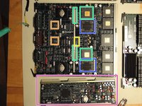
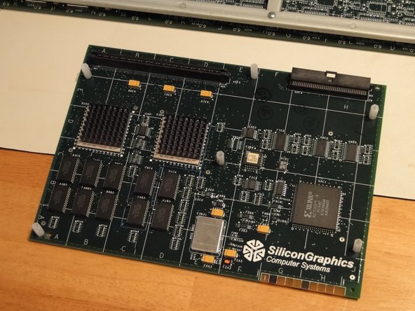
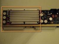
The geometry engine board contains 4 SiliconGraphics GE12 geometry processors
-
PowerChannel2 bus interface ASICs, FIFOs, and glue logic
-
geometry performance of 10M polys/sec - on par with the much newer Nvidia GeForce 256!
-
Empty solder pads. A GE with 8 processors was never created. Warm up the wave soldering oven, I smell an upgrade.
-
The graphics boards require 3.3 volts, and their power converters are on the opposite side of the backplane, on their own daughterboards.
-
-
-
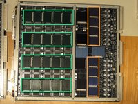
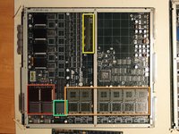
The raster manager processes the image raster and also provides texturing capabilities.
-
the RM6 is available with 16 or 64MB texture memory, this is a 16MB version.
-
InfiniteReality can run with 1, 2, or 4 RM boards. Raster memory will increase in size with additional boards; texture memory increases in speed via interleaving.
-
8 TM ASICs control 32 SDRAMs (on the back of the board) which make up the texture memory
-
80 "image engines" are on 20 quad-core ASICs. These control the raster memory (framebuffer) as well as providing many image operations such as blending, dithering, etc. They can be thought of as a precursor to the "shaders" or "stream processors" on a modern day GPU
-
With a fully-realized modern InfiniteReality4 system (with 4 RM boards per pipe and 16 pipes in a system), the system can contain up to 16GB texture memory and 160GB of framebuffer!
-
This makes for very nice pictures even on IMAX-sized curved screens with many projectors blended together to form a single image.
-
Such a system will fill many computer racks. They are still in commercial use throughout the world.
-
-
-
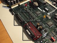
The display generator combines data from the raster managers and contains the DACs necessary to drive video output as well as 2 graphics outputs.
-
This DG4-2 contains circuitry necessary to drive 2 graphics monitors.
-
This DAC drives the video output, so InfiniteReality can output to a television or VCR via svideo or composite (BNC and RCA) connectors.
-
The optional DG4-8 can drive up to 8 graphics monitors. Outputs 2-7 have a reduced pixel clock of 180 MHz, whereas 0-1 run up to 220 MHz.
-
Sirius Video is an advanced video interface providing real-time video input, output, video-to-texture, and DMI capability. The daughterboard connects here.
-
The PAB2 Sirius Video daughterboard contains two ASICs and an FPGA. It is used to send graphics information from the InfiniteReality pipe to the Sirius Video VME motherboard. This Onyx does not have the full Sirius Video outfit, only the PAB2 daughterboard.
-
-
-
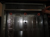
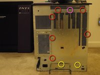
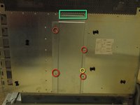
Removing the backplane cover:
-
Remove these screws fully
-
Back the bottom screws out, but don't remove them
-
Remove the top screw last. This will hold the cover in place until you are ready to remove it.
-
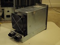
Power supply connections
-
System Controller, SCSI power, and blower connections
-
From left to right: graphics power converters (2), VME/IO4 power converter, system controller
-
-
-
Each 303 power converter board has two AT&T FW300 DC-DC 3V converters on board.
-
60 A per DC brick, 120 amps per board. This is screwdriver-melting stuff!
-
The 512T power board provides 5V and 12V DC to the VME bus and IO4 board.
-
The system controller has it's own power converter as well as:
-
Dallas RTC and NVRAM
-
system controller EPROM
-
Motorola 68hc11 MCU
-
-
-
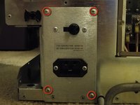
These screws hold in the circuit breaker and power receptacle assembly.
-
To remove the circuit breaker, disconnect the lines and unscrew the breakers from the panel.
-
The two lines that go to each breaker should match: blue to blue, and brown to brown.
-
The spade connectors to the circuit breaker seem to be in the advanced stages of rigor mortis, so we will not disassemble this part unless necessary.
-
-
-
There is a cover on the right side of the chassis. Behind it, the SCSI backplane, auxillary fan, and line supply connections can be accessed.
-
4 screws secure the cover
-
This guide post holds the cover in place when the screws have been removed
-
The cover has a tab at the top. Slide it out and down to remove it.
-
With the cover removed
-
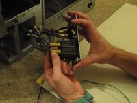
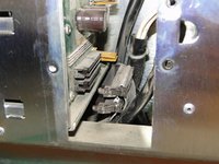
This screw holds the auxillary fan in place. The fan power connector plugs into the SCSI backplane.
-
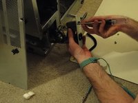
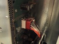
These screws hold the line supply connections in place. These connect to the system backplane and mains circuit breaker
-
These screws hold in the SCSI backplane. Remove the SCSI bus connections and power connector and hold them out of the way when removing the SCSI backplane. Remove SCSI devices before removing the backplane.
-
-
-
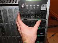
The SCSI devices are mounted on sleds. The sled can hold 3.5 inch and 5.25 inch devices.
-
Full-height devices can be accommodated but the bay above the bay in use will be inaccessible.
-
To remove a sled, slide the green lever to the left.
-
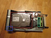
This sled holds the system disk, a 10k RPM 9GB Quantum. Slow and small by today's standard, it is typical for late 90s technology.
-
The sled's power connection.
-
Bus 0 connection (single-ended)
-
Bus 1 connection (differential signaling)
-
The Device ID can be set through a switch on the front panel. This switch plugs into the disk.
-
-
-
It is only necessary to remove the top skin when changing the top skin
-
To remove the purple top hat, lift the front of the part and slide it back. Then lift off.
-
To remove the top skin, remove both side skins. Slide a blade screwdriver into the tab on the right side of the skin, and push the skin to the left.
-
The top skin will lift off. Our machine is looking quite threadbare now.
-
-
-
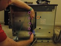
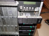
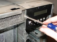
The system controller/ operator panel is held in place with one screw
-
Remove the screw and pull the panel out of it's tabs.
-
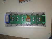
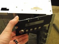
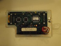
The system controller contains a keyswitch to start and stop the machine, a LCD display that shows a nifty CPU usage graph when running, and 4 operator buttons to control the system controller.
-
This console can display fan speed and temperature, power supply voltages, and logged error messages.
-
How many computers do you know of that start up with an ignition key? :)
-
-
-
What's for dinner? Graphics Supercomputer!
-
When your onyx has been re-assembled, it is a good idea to check out the machine, and make sure all components are working properly.
-
The power-on BIST does a good job of testing the memory and CPUs.
-
To fully test the graphics system, run irsaudit from a serial terminal. The full path is /usr/diags/IR/bin/irsaudit.
-


3条评论
I'll see your SGI Onyx and raise you an SGI crimson-1300, Asleep in storage, and My 3 Indigos, and several Indys we used as print servers. I miss those old Guys.
Thank you for the memory
pat saturn - 回复
Just about done doing a breakdown and cleanout of an Onyx I picked up a couple of weeks ago, thanks for the guide!
I love these machines, never had one, but i’ve had Indy R5k and Indigo2. The level of engineering is incredible.