跳转到主内容

iMac 27" 2017 Logic Board Assembly Replacement

仅作为前提条件
本指南仅用作其他指南的先决条件。不能单独食用。

你所需要的

  1. iMac 27" 2017 Logic Board Assembly Replacement, Remove the logic board: 步骤 1 中的图像 1,1
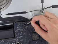
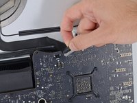
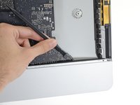
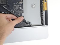
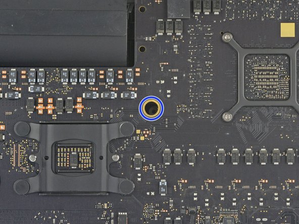
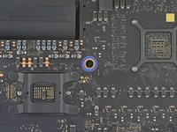
    • Use a T5 Torx screwdriver to remove the two 4 mm screws securing the AirPort/Bluetooth antenna cables.

  2. iMac 27" 2017 Logic Board Assembly Replacement: 步骤 2 中的图像 1,3 iMac 27" 2017 Logic Board Assembly Replacement: 步骤 2 中的图像 2,3 iMac 27" 2017 Logic Board Assembly Replacement: 步骤 2 中的图像 3,3
    • Use the point of a spudger to disconnect each of the four antenna connectors from the AirPort/Bluetooth card.

    • Note the original positions for each connector when reconnecting the cables. From left to right on the card, the antennas are connected in the following order:

    • Leftmost

    • Top

    • Upper right

    • Lower right

  3. iMac 27" 2017 Logic Board Assembly Replacement: 步骤 3 中的图像 1,3 iMac 27" 2017 Logic Board Assembly Replacement: 步骤 3 中的图像 2,3 iMac 27" 2017 Logic Board Assembly Replacement: 步骤 3 中的图像 3,3
    • This is a delicate connection that can be easily broken.

    • Flip up the metal retaining bracket on the iSight camera cable.

    • Pull the camera cable connector straight out of its socket, toward the top of the iMac.

  4. iMac 27" 2017 Logic Board Assembly Replacement: 步骤 4 中的图像 1,3 iMac 27" 2017 Logic Board Assembly Replacement: 步骤 4 中的图像 2,3 iMac 27" 2017 Logic Board Assembly Replacement: 步骤 4 中的图像 3,3
    • Use the flat end of a spudger to disconnect the headphone jack cable connector from its socket on the logic board.

    • Gently push the cable out of the way.

  5. iMac 27" 2017 Logic Board Assembly Replacement: 步骤 5 中的图像 1,3 iMac 27" 2017 Logic Board Assembly Replacement: 步骤 5 中的图像 2,3 iMac 27" 2017 Logic Board Assembly Replacement: 步骤 5 中的图像 3,3
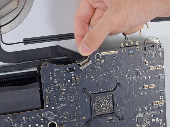
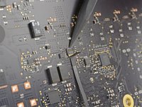
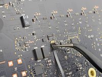
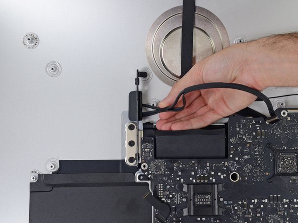
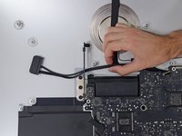
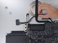
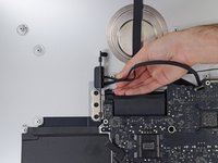
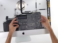
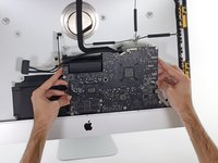
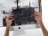
    • Use the tip of a spudger to flip open the retaining flap on the microphone ribbon cable ZIF socket.

    • Be sure you are prying up on the hinged retaining flap, not the socket itself.

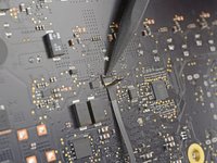
    • Use tweezers to gently pull the microphone ribbon cable straight out of its socket.

  6. iMac 27" 2017 Logic Board Assembly Replacement: 步骤 6 中的图像 1,2 iMac 27" 2017 Logic Board Assembly Replacement: 步骤 6 中的图像 2,2
    • Remove the following screws securing the logic board:

    • Two 23.7 mm T8 screws

    • One 20.1 mm T25 spacer screw

    • One 17.6 mm T8 screw

    • One 7.2 mm T8 screw

    • Three 7.1 mm T8 screws

    • One captive T8 screw

    • This screw is beneath a hole in the logic board. If you aren't using an iFixit driver, you may need an extension or a screwdriver with a longer shaft.

  7. iMac 27" 2017 Logic Board Assembly Replacement: 步骤 7 中的图像 1,3 iMac 27" 2017 Logic Board Assembly Replacement: 步骤 7 中的图像 2,3 iMac 27" 2017 Logic Board Assembly Replacement: 步骤 7 中的图像 3,3
    • Pull the hard drive SATA cable and connector through the right hard drive bracket. Move the cable to the right side of the iMac, out of the way of the exhaust port.

    • Don't attempt to completely remove the cable—it can't be removed just yet, but will get in the way of removing the logic board.

  8. iMac 27" 2017 Logic Board Assembly Replacement: 步骤 8 中的图像 1,1
    • Use a T8 Torx screwdriver to remove the two 5.6 mm screws from the top of the heat sink exhaust duct.

  9. iMac 27" 2017 Logic Board Assembly Replacement: 步骤 9 中的图像 1,3 iMac 27" 2017 Logic Board Assembly Replacement: 步骤 9 中的图像 2,3 iMac 27" 2017 Logic Board Assembly Replacement: 步骤 9 中的图像 3,3
    • When removing and installing the logic board, take care not to damage the delicate microphone ribbon cable at the bottom left of the board.

    • Tilt the logic board slightly forward.

    • Lift the logic board straight up and out of the iMac. Be careful not to snag it on any of the screw posts attached to the inside of the rear case.

  10. iMac 27" 2017 Logic Board Assembly Replacement: 步骤 10 中的图像 1,2 iMac 27" 2017 Logic Board Assembly Replacement: 步骤 10 中的图像 2,2
    • When reassembling your iMac, be very careful to align the exterior I/O ports correctly. The logic board can sit crooked even when secured with all its screws.

    • You can use a USB flashdrive or ethernet cable to ensure the logic board is seated correctly while you screw it in.

结论

To reassemble your device, follow these instructions in reverse order.

Adam O'Camb

于04/11/15注册

195,355 声望

创作了416篇指南

0条评论

添加评论

浏览统计数据:

过去 24 小时: 0

过去 7 天: 0

过去 30 天: 0

总计 74