简介
In this guide, you will be instructed how to repair a transistor in a 3 setting touch lamp. First you will need to take apart the device, followed by a small bit of circuit repair.
An indicator that a transistor has broken on a touch lamp is that it will revert to static “on” and “off“ options.
It is important to note that this is also a general guide, and will not necessarily match your lamp. If you do not already have a replacement transistor ready to use, follow the guide to step 4 and look on the transistor for its specifications so that a replacement can be ordered.
Be sure to unplug your lamp prior to beginning the guide. Soldering is required for this guide, if you do not have soldering skills, check out the How to Solder and Desolder Connections article on the site.
你所需要的
-
-
-
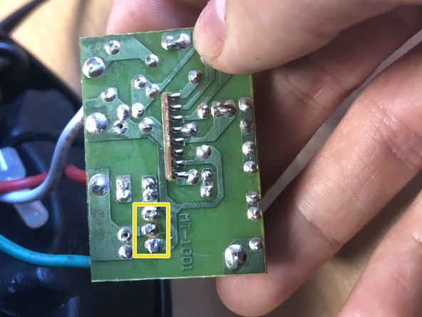
Locate the transistor.
-
Note the location of the three pins of the transistor.
-
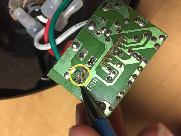
On the reverse side of the board, carefully desolder these three pins and remove the broken transistor.
-
Pay attention to the direction in which the new transistor is facing, Solder it in where the damaged one was removed. Ensure that no solder from each of the pins contact each other or any other component.
-


To reassemble your device, follow these instructions in reverse order.
To reassemble your device, follow these instructions in reverse order.
团队

Embry-Riddle Aeronautical University, Team S7-G12, Rauch Spring 2021 Embry-Riddle Aeronautical University, Team S7-G12, Rauch Spring 2021 的会员
ERAU-RAUCH-S21S7G12
1 名成员
创作了1篇指南
一条评论
The touch lamp I repaired had a slightly different lighting control box labelled MT-1009A (perhaps it was just an off/on). Anyway I followed the same procedure as above and soldered in a new 3 pin triac (BT134 PH600E) and all worked well. Good pictures, thanks