当前版本的文档还未经巡查,您可以查看最新的已查核版本 。
Using a Phillips #1 screwdriver, turn the screw on the RAM cover until you hear a click.
This is a captive panel screw and remains with the cover.
Remove the strip of plastic at the right furthermost edge of the keyboard using a plastic opening tool.
Insert the plastic opening tool at either end of the strip.
Lift upwards and proceed to the other end while repeating this lifting process every one to two inches.
CAUTION: do not allow hardware or debris into the CPU fan and duct.
Remove the two 3-mm screws at the top edge of the keyboard using a Phillips #00 screwdriver.
These are not captive panel screws and, once loosened, will be free to move about the assembly.
Gently push the two tabs locking the black ribbon cable.
To remove the black ribbon cable from the motherboard, slide the keyboard toward the screen.
You may now safely separate the keyboard from the laptop.
For the following steps, use a Phillips #1 screwdriver.
Remove the twelve 6-mm screws that border the bottom of the laptop.
Remove the 6-mm screw located in the lower middle of the device.
Remove the three 3-mm screws located in the battery bay.
Remove the one 4-mm screw located near the RAM.
CAUTION: do not allow hardware or debris into the CPU fan and duct.
Use a Phillips #1 screwdriver to remove the five 6-mm screws in the keyboard slot.
These are not captive panel screws and, once loosened, will be free to move about the assembly.
Lock the white ribbon cable into place by gently pulling on the two black tabs.
Remove the white ribbon cable by pulling it towards you.
Remove the connector that has the blue, red, black, and white wires using tweezers.
Using tweezers, remove two connectors: one with black and white wires and one with green, yellow, red, black, and white wires.
Using your fingers, remove the large connector from the top right corner of the motherboard.
Using the Phillips #1 or Phillips #00 screwdriver, remove the two 3-mm screws from the card with black and white wires coming off of it.
Our card has one screw that required a Philips #1 and one that required a Philips #00. Start with the Philips #1 and, if it doesn't fit, use the Philips #00.
The card should pop up. Gently remove the card with your fingers.
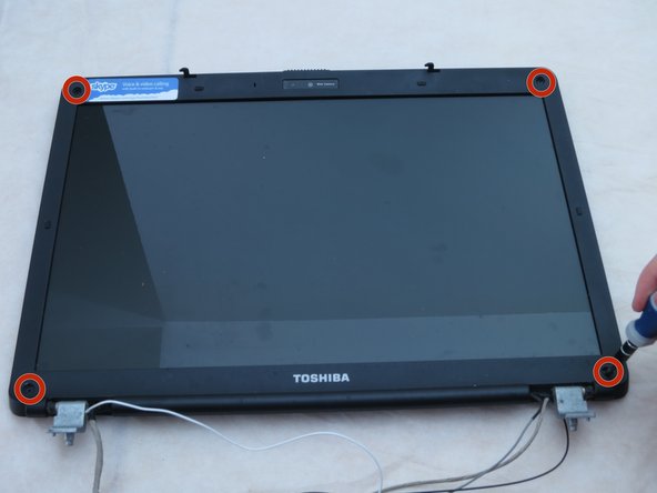
Using a Phillips #1 screwdriver, remove the four 4-mm screw.
Using a Philips #1 screwdriver, remove the one 6-mm screw.
Using your hands, remove the small connectors from the small board attached to the bottom of the LCD screen.
In order to access the second connector, you will need to remove the protective plastic cover. Make sure to put this back on when installing the next screen.
Using a Phillips #1 screwdriver, remove the six 3-mm screws from the sides of the screen. There should be three on each side.
Using your hands, remove the two metal strips the screws were holding.
嵌入本指南
选择一个尺寸并复制下面的代码,将本指南作为一个小插件嵌入到你的网站/论坛中。
单个步骤
完整指南
小——600像素
中——800像素
大——1200像素
预览