跳转到主内容
加入维修社区 - 创建账户

Sony SRS-XB43 LED Module Replacement

你所需要的

    1. Sony SRS-XB43 LED Module Replacement, Faceplate: 步骤 1 中的图像 1,2 Sony SRS-XB43 LED Module Replacement, Faceplate: 步骤 1 中的图像 2,2
      • Insert the metal spudger into the mesh's seam/opening located at the bottom of the speaker.

      • Begin applying pressure, prying along the run of the seam until the mesh cover begins to come loose.

      • Fully open the hinged mesh cover and pry it off the unit.

      询问修复机器人

      添加评论

    2. Sony SRS-XB43 LED Module Replacement: 步骤 2 中的图像 1,1
      • Turn the speaker so the back is facing you.

      • Remove the factory tamper seal below the speaker volume toggle to reveal a single screw.

      • Remove the single screw using a T8 Torx.

      询问修复机器人

      添加评论

    3. Sony SRS-XB43 LED Module Replacement: 步骤 3 中的图像 1,1
      • Remove all ten screws using a Phillips #1 screwdriver.

      询问修复机器人

      添加评论

    4. Sony SRS-XB43 LED Module Replacement: 步骤 4 中的图像 1,2 Sony SRS-XB43 LED Module Replacement: 步骤 4 中的图像 2,2
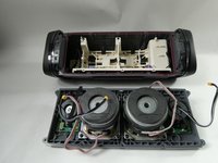
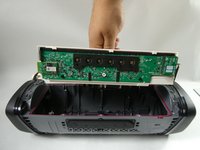
      • Slowly lift the speaker face off of the housing unit.

      • Unplug the six wires connecting the faceplate to the motherboard.

      询问修复机器人

      添加评论

    1. Sony SRS-XB43 LED Module Replacement, Battery: 步骤 5 中的图像 1,2 Sony SRS-XB43 LED Module Replacement, Battery: 步骤 5 中的图像 2,2
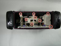
      • Orient the speaker's backplate so that the plastic chassis and internal electronics are facing upwards.

      • Remove the eight 10 mm screws securing the motherboard chassis to the backplate using a Phillips #1 screwdriver.

      • Grab the motherboard chassis and gently remove it from the backplate of the speaker.

      询问修复机器人

      添加评论

    2. Sony SRS-XB43 LED Module Replacement: 步骤 6 中的图像 1,3 Sony SRS-XB43 LED Module Replacement: 步骤 6 中的图像 2,3 Sony SRS-XB43 LED Module Replacement: 步骤 6 中的图像 3,3
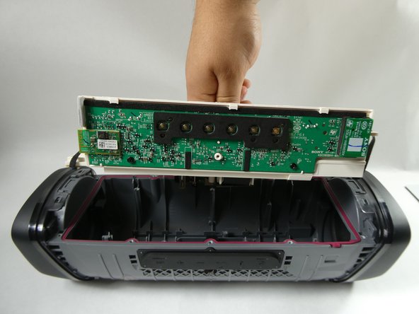
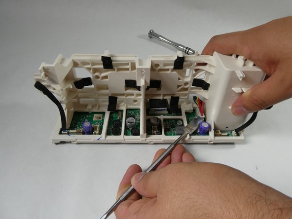
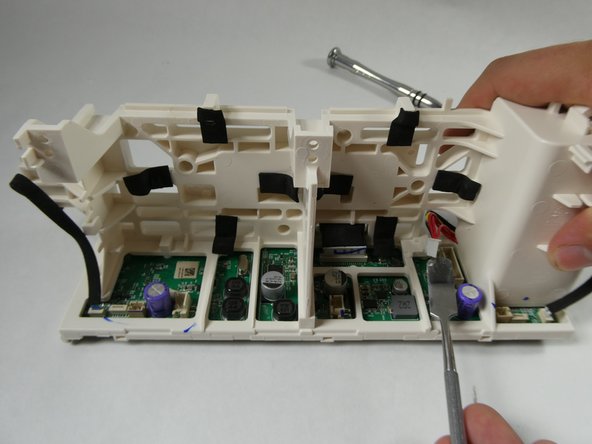
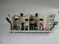
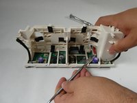
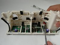
      • Orient the motherboard chassis so that the side with the six buttons is facedown on the table and the opposite side is visible to you.

      • Disconnect the seven-prong cable (the one with red, yellow, and black wires) plugged into the motherboard by prying on its edge/extruding lip with a spudger.

      添加评论

    3. Sony SRS-XB43 LED Module Replacement: 步骤 7 中的图像 1,2 Sony SRS-XB43 LED Module Replacement: 步骤 7 中的图像 2,2
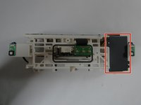
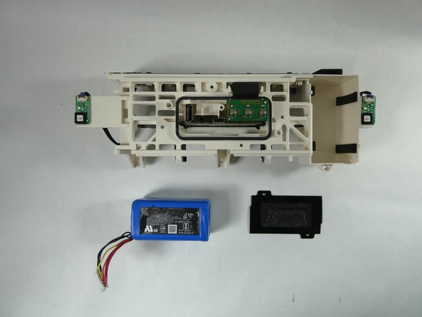
      • Orient the plastic chassis so that the port housing PCB is facing upward.

      • Remove the plastic black film covering the battery, leaving the blue battery exposed.

      添加评论

    4. Sony SRS-XB43 LED Module Replacement: 步骤 8 中的图像 1,2 Sony SRS-XB43 LED Module Replacement: 步骤 8 中的图像 2,2
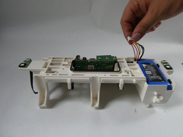
      • Lightly pull the seven-prong cable upwards until the battery is angled in such a way that you can get a proper grip on both sides with your fingers.

      • Using your fingers, pull upwards until the battery is removed from its enclosure.

      • Do not use a spudger or other flat tools to pry in between the seam of the battery and the battery compartment, as it is possible to damage the battery.

      添加评论

    1. Sony SRS-XB43 LED Module Replacement, LED Module: 步骤 9 中的图像 1,1
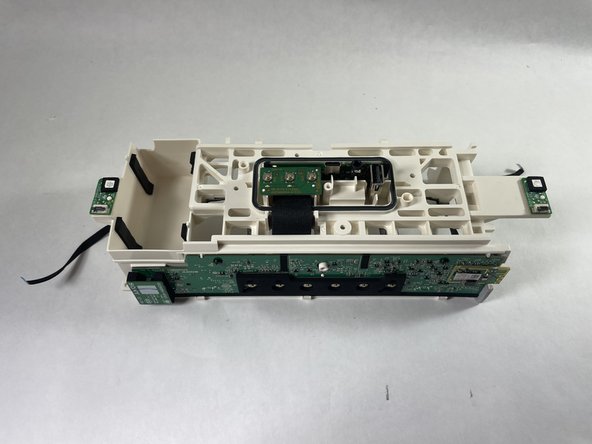
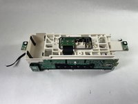
      • Orient the motherboard chassis so that the battery compartment is facing upwards.

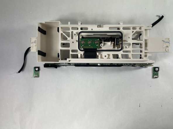
      • Identify the two LED control PCBs located on the left and right edges of the plastic chassis.

      添加评论

    2. Sony SRS-XB43 LED Module Replacement: 步骤 10 中的图像 1,3 Sony SRS-XB43 LED Module Replacement: 步骤 10 中的图像 2,3 Sony SRS-XB43 LED Module Replacement: 步骤 10 中的图像 3,3
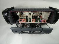
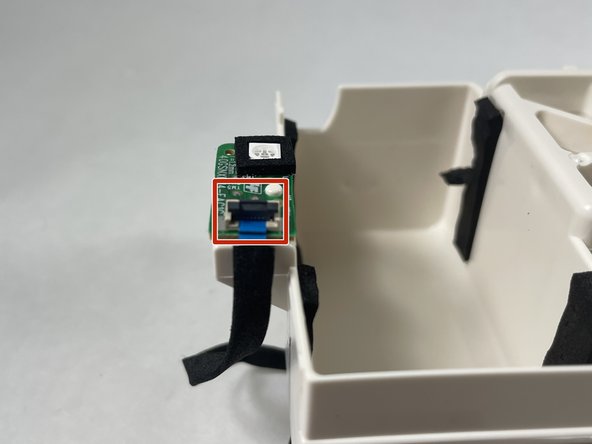
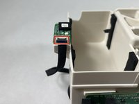
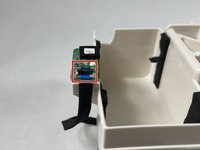
      • Identify the black latch on each of the plugs that are connected to the PBCs.

      • Swing the black latch open by gently prying the front/extruding lip of the plug with a spudger or other flat tool.

      • To give a sense of direction, the latch should swing away from you or towards the LED (metallic square).

      • Grab each ribbon cable and apply a horizontal pulling force (with respect to the LED control PCBs) to disconnect them from the connectors.

      询问修复机器人

      添加评论

    3. Sony SRS-XB43 LED Module Replacement: 步骤 11 中的图像 1,3 Sony SRS-XB43 LED Module Replacement: 步骤 11 中的图像 2,3 Sony SRS-XB43 LED Module Replacement: 步骤 11 中的图像 3,3
      在这个步骤中使用的工具:
      Plastic Cards
      $2.99
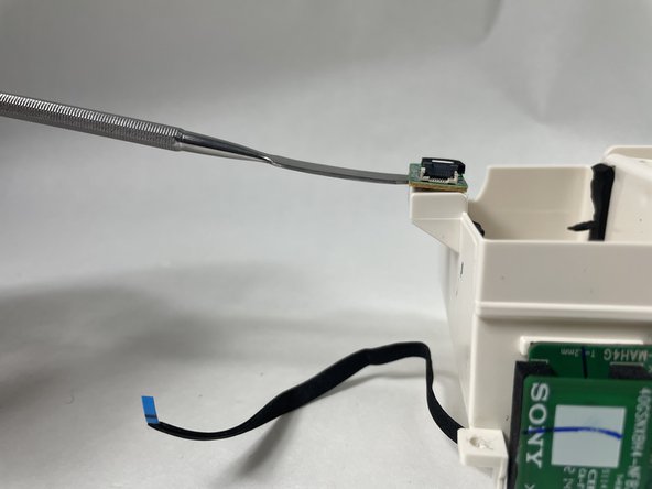
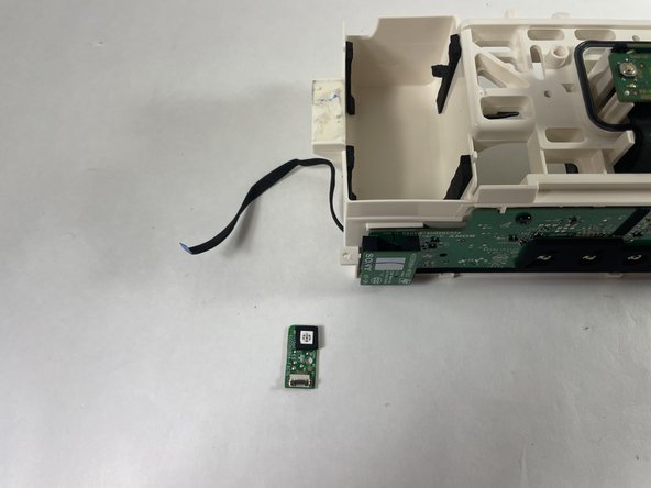
      • Insert the spudger below the LED control PCBs and pry to remove it from the plastic chassis.

      • The PCBs are held onto the chassis with a considerably strong double-sided tape. If the spudger is too thick and can not fit under the PCBs, use a thin plastic pick or plastic card.

      询问修复机器人

      添加评论

结论

To reassemble your device, follow these instructions in reverse order.

取消:我没有完成这个指南。

2等其他人完成本指南。

团队

UMass Dartmouth, Team 3-5, Botvin Fall 2022 UMass Dartmouth, Team 3-5, Botvin Fall 2022 的会员

UMASSD-BOTVIN-F22S3G5

4 名成员

创作了10篇指南

1指南评论

i need email to contact You please

Danny Bryan Vega - 回复 分享
添加评论

浏览统计数据:

过去 24 小时: 1

过去 7 天: 9

过去 30 天: 39

总计 982