跳转到主内容

当前版本的文档还未经巡查,您可以查看最新的已查核版本

你所需要的

  1. , 电池: 步骤 1 中的图像 1,1
    • 旋转电脑,使螺丝所在的一行位于远离您的一侧。

    • 将两个电池卡扣拉开,使电池的边缘抬起。

    • 取出电池。

  2. 这个步骤还没有翻译 帮忙翻译一下

    : 步骤 2 中的图像 1,1
    • Remove the three identical Phillips screws from the memory door.

  3. 这个步骤还没有翻译 帮忙翻译一下

    : 步骤 3 中的图像 1,1
    • Lift the memory door up enough so that you can get a grip on it, and slide it toward you, pulling it away from the casing.

  4. 这个步骤还没有翻译 帮忙翻译一下

    : 步骤 4 中的图像 1,1
    • Release the tabs on each side of the RAM chip at the same time. These tabs lock the chip in place and releasing them will cause the chip to "pop" up.

    • Pull the chip directly out from its connectors. If there is a second RAM chip installed, pop it out in the same manner.

  5. 这个步骤还没有翻译 帮忙翻译一下

    • This is a diagram of the trackpad ribbon clamp connector you will disconnect in the next step.

    • 1) With your fingernails, grasp the locking bar on either side slide it a small amount (about 1/16" or 2 mm) towards the battery.

    • 2) After disengaging the locking bar, slide the cable out of the connector.

  6. 这个步骤还没有翻译 帮忙翻译一下

    : 步骤 6 中的图像 1,1
    • For this step, you only need to move the connector about 2 mm. Pulling too hard or too far will damage the connector.

    • Loosen the trackpad connector by pulling the locking bar toward the battery housing, using the tips of your fingers.

    • Slide the trackpad cable out of the loosened connector.

    • When reattaching the trackpad ribbon cable, make sure that the orange cable is slid into the connector above the locking bar.

    • Note: When reassembling the case, the trackpad cable can get stuck below the slot to the motherboard. It's possible to nudge it out slowly by gently prodding it on either side with a small screwdriver. You don't need to use much force to do this. Eventually it will just pop back out and you can reconnect as per the instructions above. Also, note that the locking bar comes loose so if you see a little piece of plastic lying around when reassembling, that's what it is. :)

  7. 这个步骤还没有翻译 帮忙翻译一下

    : 步骤 7 中的图像 1,1
    • Remove the following 10 screws from the bottom case:

    • Three 1.7 mm Phillips from the front edge of the battery compartment.

    • One 3.9 mm T8 Torx to the right of the memory card.

    • One 6.9 mm T8 Torx at the left edge of the memory compartment.

    • Three 12.4 mm fully threaded Phillips from the center of the row of screws along the back edge of the case.

    • Two 15.1 mm 2.5 mm threaded Phillips, one from either end of the row of screws along the back edge of the case.

  8. 这个步骤还没有翻译 帮忙翻译一下

    • Turn the computer over and rotate it so that the DVI port faces you.

    • Remove the four identical Phillips screws spread along this edge of the case.

  9. 这个步骤还没有翻译 帮忙翻译一下

    • Turn the computer 180 degrees so that the power receptacle faces you, and remove the four Phillips screws (identical to those in the last step).

  10. 这个步骤还没有翻译 帮忙翻译一下

    : 步骤 10 中的图像 1,1
    • Open the computer and turn it so that the screen faces you.

    • Pull the upper case off, lifting from the back, and working around the edges.

  11. 这个步骤还没有翻译 帮忙翻译一下

    : 步骤 11 中的图像 1,1
    • Use a spudger to loosen the casing if it sticks.

    • Once the casing is entirely free, lift it off of the computer.

  12. 这个步骤还没有翻译 帮忙翻译一下

    : 步骤 12 中的图像 1,1
    • If you are ultimately removing the heat sink & fan assembly, your computer will differ from the images in this section.

    • Disconnect the inverter cable, the Bluetooth/DC-In cable, and the display data cable from the logic board.

  13. 这个步骤还没有翻译 帮忙翻译一下

    : 步骤 13 中的图像 1,1
    • Disconnect the Airport antenna cable at the gold connector, making sure you pull only on the gold metal portion of the connector.

  14. 这个步骤还没有翻译 帮忙翻译一下

    : 步骤 14 中的图像 1,1
    • Disconnect the Bluetooth antenna cable from the Bluetooth board.

  15. 这个步骤还没有翻译 帮忙翻译一下

    : 步骤 15 中的图像 1,1
    • Remove one T6 Torx screw from the upper, left corner of the left fan, and one from the upper, right corner of the right fan (2 screws total).

  16. 这个步骤还没有翻译 帮忙翻译一下

    : 步骤 16 中的图像 1,1
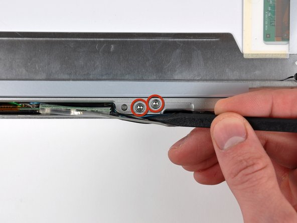
    • From each complete hinge assembly, remove two Torx T6 screws from the outside of each set, leaving two remaining in the middle of each hinge. On each side, the two screws closer to the edge of the computer are shorter than the two screws closer to the center of the computer. Then remove the two inner screws from each hinge assembly. There are 8 screws total.

  17. 这个步骤还没有翻译 帮忙翻译一下

    : 步骤 17 中的图像 1,1
    • Lift the screen assembly away from the computer.

  18. 这个步骤还没有翻译 帮忙翻译一下

    : 步骤 18 中的图像 1,1
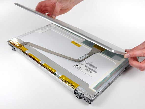
    • When reassembling the display, check to see that the hinges are seated properly before reinstalling the 8 screws of the two hinges. There is a metal phalange on the inside end of each hinge assembly that must be pointed downward and fit into a slot below the inside edge of the hinge. If not, the inside end of each hinge will sit too high and the plastic retaining bracket for the wiring will not sit down properly.

  19. 这个步骤还没有翻译 帮忙翻译一下

    : 步骤 19 中的图像 1,2 : 步骤 19 中的图像 2,2
    • Remove the single Phillips screw from the lower left and right corners of the display.

  20. 这个步骤还没有翻译 帮忙翻译一下

    : 步骤 20 中的图像 1,1
    • The picture at left (rear panel already removed) shows the locations of the metal clips (shown in red) that snap on to the front display bezel. In the next few steps, you will use a small flathead screwdriver to release these clips from a ridge around the perimeter of the front display bezel.

    • When prying in the following steps, be sure not to damage the antenna cables that run around the perimeter of the front display bezel.

  21. 这个步骤还没有翻译 帮忙翻译一下

    : 步骤 21 中的图像 1,3 : 步骤 21 中的图像 2,3 : 步骤 21 中的图像 3,3
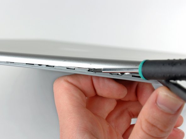
    • Insert the flat end of a spudger between the front display bezel and the plastic rim attached to the rear bezel near the lower right corner of the display.

    • Do not try to insert the spudger between the front display bezel and its plastic surround.

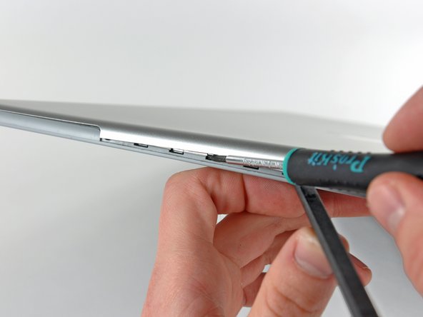
    • While carefully prying the rear display bezel away from the display assembly, use a small flathead screwdriver to pry the small steel clip nearest the bottom right corner of the display away from the edge of the front display bezel.

    • Repeat the above procedure until you've released all the clips along the right side of the display.

  22. 这个步骤还没有翻译 帮忙翻译一下

    : 步骤 22 中的图像 1,1
    • Slightly lift the recently-freed corner of the rear display bezel to separate the clips along the span of the clutch hinges.

  23. 这个步骤还没有翻译 帮忙翻译一下

    : 步骤 23 中的图像 1,1
    • Insert the flat end of a spudger between the rear display bezel and the plastic surround of the front display bezel near the lower left corner of the display.

    • Carefully pry the rear display bezel away from the front display bezel to release a metal clip.

  24. 这个步骤还没有翻译 帮忙翻译一下

    : 步骤 24 中的图像 1,1
    • Repeat the previous procedure to release the clips along the left side of the rear display bezel.

  25. 这个步骤还没有翻译 帮忙翻译一下

    : 步骤 25 中的图像 1,2 : 步骤 25 中的图像 2,2
    • Slightly lift the lower edge of the rear display bezel and push it toward the top edge of the display, releasing the clips along the top edge of the rear display bezel.

    • Remove the rear display bezel and set it aside.

  26. 这个步骤还没有翻译 帮忙翻译一下

    : 步骤 26 中的图像 1,1
    • Remove the pieces of tape along the lower edge of the display that are covering the opening of the clutch hinges.

  27. 这个步骤还没有翻译 帮忙翻译一下

    : 步骤 27 中的图像 1,1
    • Remove the two 10.3 mm T8 Torx screws securing the left side of the clutch hinges to the front bezel.

  28. 这个步骤还没有翻译 帮忙翻译一下

    : 步骤 28 中的图像 1,1
    • Remove the two 10.3 mm T8 Torx screws securing the center of the clutch hinges to the front bezel.

  29. 这个步骤还没有翻译 帮忙翻译一下

    : 步骤 29 中的图像 1,1
    • Remove the two 10.3 mm T8 Torx screws securing the right side of the clutch hinges to the front bezel.

    • Pull the clutch cover away from the positioning posts holding it on the front display bezel.

  30. 这个步骤还没有翻译 帮忙翻译一下

    : 步骤 30 中的图像 1,1
    • Use the tip of a spudger to pop the plastic end cap off the left side of the clutch cover.

  31. 这个步骤还没有翻译 帮忙翻译一下

    : 步骤 31 中的图像 1,1
    • Remove the display inverter assembly from its recess in the clutch cover.

  32. 这个步骤还没有翻译 帮忙翻译一下

    : 步骤 32 中的图像 1,1
    • Use the tip of a spudger to remove the plastic end cap from the right side of the clutch hinges.

  33. 这个步骤还没有翻译 帮忙翻译一下

    : 步骤 33 中的图像 1,1
    • Carefully slide the display data cable out of its channel in the clutch hinges.

    • Repeat this process for the inverter/AirPort cables. Once the clutch hinge assembly is completely free from the display, lift it off the front display bezel.

终点

附加文件

0条评论

添加评论

浏览统计数据:

过去 24 小时: 0

过去 7 天: 0

过去 30 天: 2

总计 4,462