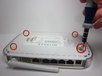
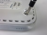
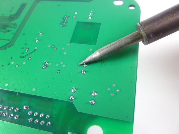
跳转到主内容

NETGEAR WGT624 v3 Capacitor Replacement

你所需要的

  1. NETGEAR WGT624 v3 Capacitor Replacement, Lower Case: 步骤 1 中的图像 1,1
    • Turn the device so that the bottom is facing up.

  2. NETGEAR WGT624 v3 Capacitor Replacement: 步骤 2 中的图像 1,3 NETGEAR WGT624 v3 Capacitor Replacement: 步骤 2 中的图像 2,3 NETGEAR WGT624 v3 Capacitor Replacement: 步骤 2 中的图像 3,3
    • Use the plastic opening tool to carefully lift the rubber stops in each corner.

    • Do not completely remove the rubber stops, because they are difficult to replace.

  3. NETGEAR WGT624 v3 Capacitor Replacement: 步骤 3 中的图像 1,2 NETGEAR WGT624 v3 Capacitor Replacement: 步骤 3 中的图像 2,2
    • Unscrew the 4 11.8 mm T-8 Torx screws from each corner of the device.

  4. NETGEAR WGT624 v3 Capacitor Replacement: 步骤 4 中的图像 1,2 NETGEAR WGT624 v3 Capacitor Replacement: 步骤 4 中的图像 2,2
    • Lift the lower case straight up from the rest of the router.

  5. NETGEAR WGT624 v3 Capacitor Replacement, Motherboard: 步骤 5 中的图像 1,2 NETGEAR WGT624 v3 Capacitor Replacement, Motherboard: 步骤 5 中的图像 2,2
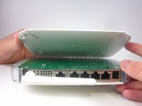
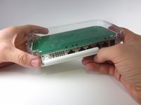
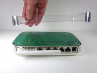
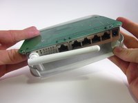
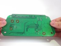
    • Remove the clear plastic casing by lifting it straight up from the router.

  6. NETGEAR WGT624 v3 Capacitor Replacement: 步骤 6 中的图像 1,2 NETGEAR WGT624 v3 Capacitor Replacement: 步骤 6 中的图像 2,2
    • Separate the motherboard from the top shell by lifting it straight up from the router.

  7. NETGEAR WGT624 v3 Capacitor Replacement, Capacitor: 步骤 7 中的图像 1,1
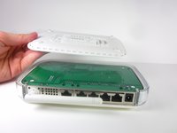
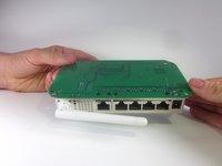
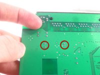
    • Turn the motherboard so that the top is facing upwards.

    • Place the motherboard on a clean flat surface.

  8. NETGEAR WGT624 v3 Capacitor Replacement: 步骤 8 中的图像 1,1
    • Locate the four capacitors.

  9. NETGEAR WGT624 v3 Capacitor Replacement: 步骤 9 中的图像 1,2 NETGEAR WGT624 v3 Capacitor Replacement: 步骤 9 中的图像 2,2
    • Turn the motherboard so that the bottom is facing upwards.

    • Locate the two soldered contacts for each capacitor.

  10. NETGEAR WGT624 v3 Capacitor Replacement: 步骤 10 中的图像 1,2 NETGEAR WGT624 v3 Capacitor Replacement: 步骤 10 中的图像 2,2
    • Do not refer to the pictures in this step for correct soldering and de-soldering techniques. They are solely for illustration purposes.

    • Desolder the soldered connections between the capacitors and the motherboard, and pull the capacitor from the motherboard.

    • For proper soldering and de-soldering techniques, refer here.

    • When reinstalling the capacitor, make sure the negative side of the capacitor is aligned with the shaded white region of the circle.

结论

To reassemble your device, follow these instructions in reverse order.

另外一个人完成了本指南。

团队

Cal Poly, Team 3-31, Amido Winter 2013 Cal Poly, Team 3-31, Amido Winter 2013 的会员

CPSU-AMIDO-W13S3G31

3 名成员

创作了12篇指南

一条评论

my router NETGEAR WNR 612 WIFI LED NOT GLOWING PLEASE HLP ME IN REPAIRING

Vinod Kumar Polakonda - 回复

添加评论

浏览统计数据:

过去 24 小时: 1

过去 7 天: 3

过去 30 天: 6

总计 1,508