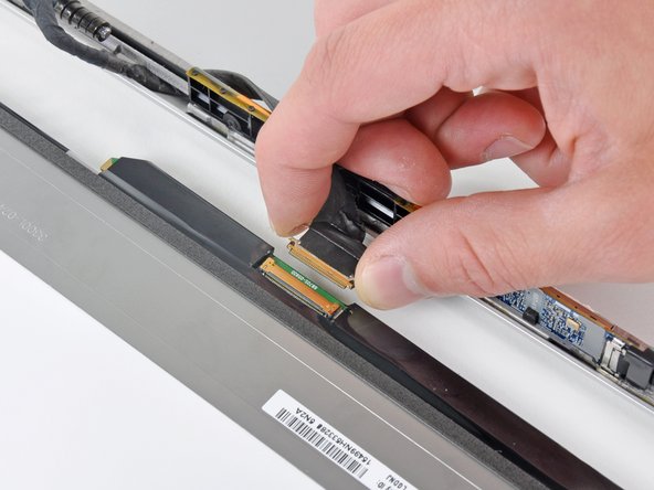
Grab the plastic pull tab secured to the LVDS cable lock and rotate it toward the DC-in side of the computer.
Pull the LVDS connector straight away from its socket.
When disconnecting the LVDS cable, do not pull on the black tab secured to the LVDS cable lock. We recommend wiggling the cable while applying tension to slowly "walk" the connector out of its socket.
Be sure to hold the display and upper case together with your other hand. Failure to do so may cause the freed display/upper case to fall, potentially damaging each component.
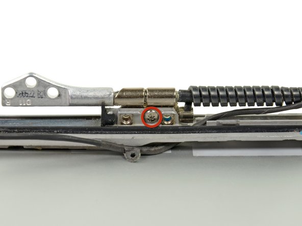
Remove the last remaining 6 mm Torx screw securing the display to the upper case.
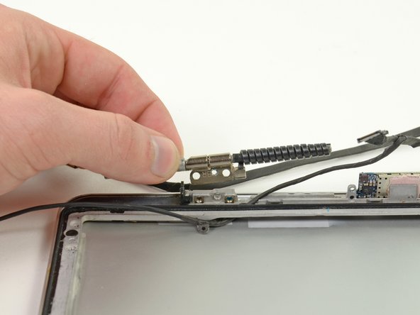
Grab the upper case with your right hand and rotate it slightly toward the top of the display so the upper display bracket clears the edge of the upper case.
Rotate the display slightly away from the upper case.
Lift the display away from the upper case, minding any brackets or cables that may get caught.
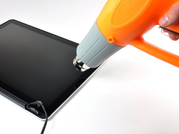
In the following steps, you will use a heat gun to soften the adhesive securing the outer black border around the underside of the front glass panel to the display. The area the adhesive is applied to is shown in red in the second picture.
Before starting, be sure to clean the display glass with lint-free cloth moistened with a mild solution; it will make the suction cup adhere better, and will make checking for dust on reassembly easier
With the heat gun set to low, start by heating the outer black border near the upper right corner of the glass panel.
Always aim the heat gun away from the soft rubber strip around the display glass. Heating the rubber will cause it to melt slightly, turning its finish from matte to glossy. Touching overheated rubber can cause it to permanently deform.
Due to the heat applied, it is normal for a layer of condensation to develop on the inside of the glass panel and/or the outside of the LCD. It can be removed with glass cleaner once the glass is separated from the display.
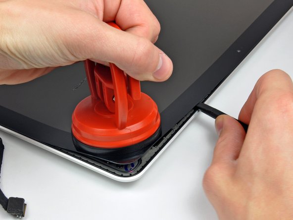
With the panel sufficiently heated, fasten a heavy-duty suction cup near the upper right corner of the display glass.
Don't fasten the suction cup on top of the rubber strip around the edge of the display glass.
To attach the suction cups we sell, first position the suction cup with the movable handle parallel to the face of the glass panel. While lightly holding the suction cup against the glass, raise the movable handle until it is parallel with the other handle.
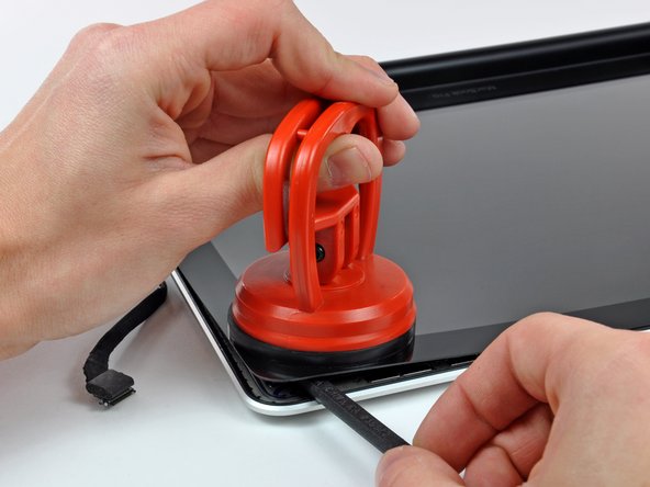
Slowly and gently pull the corner of the display glass up off the display assembly.
If only the top edge of the glass lifts up (as seen in the third picture), repeat steps one and two until you can lift up the corner of the panel.
Use a heat gun to soften the adhesive under the black strip along the right side of the front glass panel.
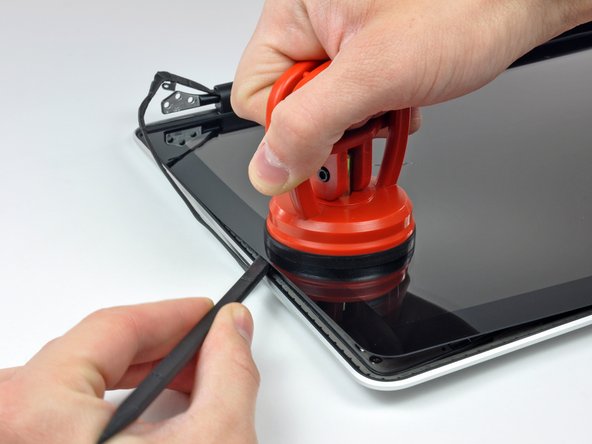
Attach a suction cup along the right side of the front glass panel.
Pull up on the glass panel while you use the flat end of a spudger to separate it from the rest of the display assembly.
Continue working along the right edge of the front display glass until it is separated from the display.
It may be helpful to use a guitar pick or another thin plastic object to keep the upper right corner of the front glass panel from sticking back down to the display assembly.
Use a heat gun to soften the adhesive under the black strip near the upper left corner of the glass display panel.
Attach a suction cup near the upper left corner of the glass display panel.
Pull up on the suction cup and use the flat end of a spudger to carefully pry the glass display panel out of the display assembly.
Once the upper left corner has been separated from the display, it may be helpful to use a guitar pick or another thin plastic object to keep the glass from sticking back down to the display assembly.
Now that the top, left, and right edges of the glass are free from the display, slowly lift the top edge of the glass panel and gently rotate it out of the display.
If necessary, use the flat end of a spudger to free the bottom edge of the glass display panel from the display assembly.
Before reassembling, be sure to clean both the inside of the glass display panel and the LCD as any dust or fingerprints trapped inside will be annoyingly visible when the machine is on.
Insert the edge of a plastic opening tool between the display glass and the camera bracket, and run it around the camera bracket to separate it from the display glass.
Do not forget to stick the camera bracket down to the new front display glass before reassembly.
During the glass removal process, the camera cable may stick to the adhesive on the glass panel, disconnecting it from the camera board as the panel is lifted. If your camera cable is still connected to the camera board, skip this step.
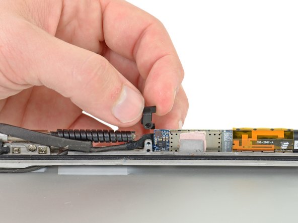
To reconnect the cable, first use the tip of a spudger to remove the piece of foam tape over the camera cable ZIF socket.
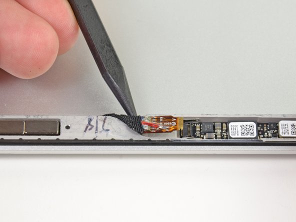
Use the tip of a spudger to flip up the ZIF cable retainer on the camera cable socket.
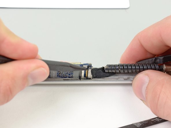
Insert the camera cable into its socket on the camera board and use the tip of a spudger to snap down the ZIF cable retainer, locking the cable in place.
Reapply the piece of tape covering the camera cable socket.
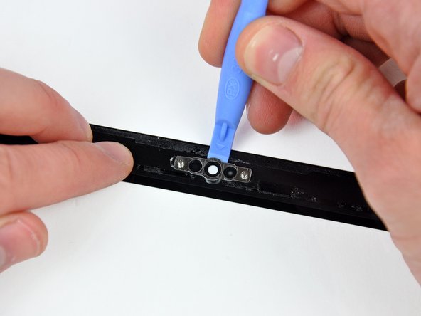
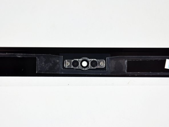
Slide the clutch cover toward the right edge of the display.
The clutch cover will move approximately .25" and stop. Do not force it too far to the right.
When reinstalling the clutch cover, be sure to slip it over the components protruding from the lower edge of the display about .25" to the right of its final installed position on the display.
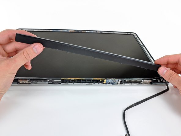
Starting at its far left end, rock the clutch cover along its long axis while pulling it away from the clutch hinge.
Working from right to left, carefully continue to release and lift the clutch along the lower edge of the display assembly.
Lift the clutch cover up off the front bezel and set it aside.
When reinstalling the clutch cover, be sure to widen the opening when slipping it over the small black plastic cosmetic cover that fills the open end of the clutch cover when it is in place. The cosmetic cover has very thin and delicate plastic arms that hold it to the right clutch hinge.
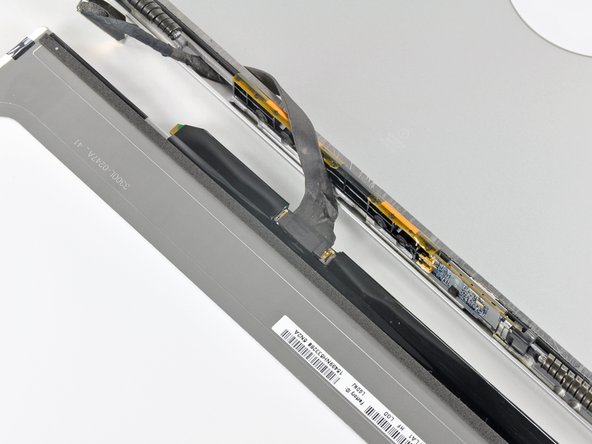
Pull the LCD toward the top edge of the display to slide the circuitry along its lower edge out of the recess in the aluminum display assembly.
It may be helpful to use one hand to feed the display data cable through its channel in the aluminum display assembly as you pull the LCD toward the top edge of the display with the other hand.
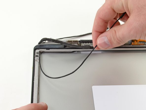
Carefully pull half of the AirPort/iSight cable through the opening located underneath the right hinge.
Do not pull the AirPort/iSight cable completely through the opening. The right hinge prevents the cable from complete removal. Forcing the cable through the opening may cause severe damage to your AirPort/iSight cable.