跳转到主内容

当前版本的文档还未经巡查,您可以查看最新的已查核版本

你所需要的

  1. , 电池: 步骤 1 中的图像 1,2 , 电池: 步骤 1 中的图像 2,2
    • 合上盖子,将Mini 1000 翻转到背面。

    • 同时向里推动两个电池释放锁。

  2. : 步骤 2 中的图像 1,1
    • 从靠近释放锁的位置将电池从Mini 1000 中提起。

  3. , 键盘: 步骤 3 中的图像 1,1
    • 移除下列螺丝

    • 一颗6mm 十字螺丝

    • 一颗4mm 十字螺丝

  4. : 步骤 4 中的图像 1,3 : 步骤 4 中的图像 2,3 : 步骤 4 中的图像 3,3
    • 为了方便拆卸键盘,建议用一只手将键盘向外推,位于Mini 1000背面的开口(第三幅图中突出显示的位置)。

    • 一只手在开口推动时,用另一只手握住键盘的左上边缘,稍微向上拉动键盘。

    • 一旦建撬开一个开口,抓住键盘,并沿着顶部边缘的上边缘缓缓向上提起它。

  5. : 步骤 5 中的图像 1,1
    • 将键盘从上盖中取出,键盘仍被线缆与主板连接。

  6. : 步骤 6 中的图像 1,1
    • 使用指甲或者撬棒的扁平一端来将ZIF滑杆推开。

    • 请确保您撬动的是滑杆而不是插座本身。

    • 从插座中拉出线缆,移走键盘。

  7. , 硬盘: 步骤 7 中的图像 1,2 , 硬盘: 步骤 7 中的图像 2,2
    • 使用指甲或者撬棒扁平一端推动SIM卡线缆 ZIF插座上的滑杆。

    • 请确保您撬动的是滑杆,而不是插座本身。

    • 将SIM卡线缆从插座中拉出,与硬盘顶部的外壳分离。

  8. : 步骤 8 中的图像 1,1
    • 使用指甲或者撬棒扁平的一端推动硬盘线缆ZIF插座上的滑杆。

    • 请确保您撬动的是滑杆而不是插座本身。

  9. : 步骤 9 中的图像 1,1
    • 移除将硬盘和后壳固定的两颗4.5mm十字螺丝。

  10. : 步骤 10 中的图像 1,2 : 步骤 10 中的图像 2,2
    • 将硬盘从后壳上提出来,小心在进行操作时不要损坏了线缆。

  11. 这个步骤还没有翻译 帮忙翻译一下

    : 步骤 11 中的图像 1,1
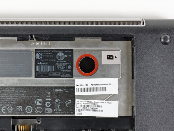
    • Using the sharp tip of a spudger, pry and remove the four plastic screw covers from the underside of the HP Mini 1000.

    • There are three different variations of the covers:

    • The two bottom covers are short in height and are notched to prevent incorrect insertion

    • The upper right cover is taller in height and is notched.

    • The upper left cover is taller in height and is not notched.

  12. 这个步骤还没有翻译 帮忙翻译一下

    : 步骤 12 中的图像 1,1
    • Remove the four 7 mm Phillips screws that secure the upper case to the lower case.

  13. 这个步骤还没有翻译 帮忙翻译一下

    : 步骤 13 中的图像 1,1
    • Flip the computer over and open the display.

    • Remove the two 4.5 mm Phillips screws securing the upper case to the lower case.

  14. 这个步骤还没有翻译 帮忙翻译一下

    : 步骤 14 中的图像 1,2 : 步骤 14 中的图像 2,2
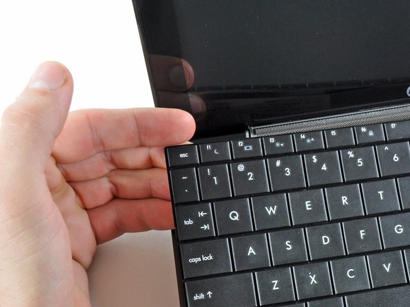
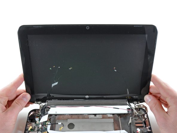
    • Wedge the flat end of a spudger in between the upper case and lower case near the bottom right corner of the display.

    • Carefully pry and rock the spudger upwards to create a small gap between the upper case and lower case.

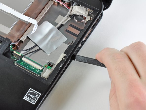
    • Continue the previously described motion along the right edge of the upper case to release the clips securing the upper case to the lower case.

  15. 这个步骤还没有翻译 帮忙翻译一下

    : 步骤 15 中的图像 1,2 : 步骤 15 中的图像 2,2
    • Repeat the same procedure as mentioned in the previous step to release the clips along the left side of the upper case.

  16. 这个步骤还没有翻译 帮忙翻译一下

    : 步骤 16 中的图像 1,1
    • Grasp the upper case and carefully lift it slightly upwards, freeing it from any remaining clips.

    • The upper case is still attached via the TouchPad ribbon cable that is connected to the motherboard. Do not remove it completely just yet.

  17. 这个步骤还没有翻译 帮忙翻译一下

    : 步骤 17 中的图像 1,1
    • Lay the upper case on top of the upper portion of the motherboard.

    • Use your fingernail or the flat end of a spudger to flip up the retaining flap on the TouchPad cable ZIF socket.

    • Be sure you are prying up on the retaining flap, not the socket itself.

    • Pull the TouchPad ribbon cable out of its socket.

    • Remove the upper case from the HP Mini 1000.

  18. 这个步骤还没有翻译 帮忙翻译一下

    : 步骤 18 中的图像 1,1
    • If present, peel the sticker up off the top of the Wi-Fi board to reveal the Wi-Fi antenna connectors.

  19. 这个步骤还没有翻译 帮忙翻译一下

    : 步骤 19 中的图像 1,3 : 步骤 19 中的图像 2,3 : 步骤 19 中的图像 3,3
    • Pry the Wi-Fi antenna connectors (2 total) up off the Wi-Fi board.

    • During reassembly, remember to correctly connect the antenna cables to their respective terminals. The green labeled antenna is connected to the "MAIN" terminal and the white labeled antenna is connected to the "AUX" terminal.

  20. 这个步骤还没有翻译 帮忙翻译一下

    : 步骤 20 中的图像 1,1
    • Remove the single 3 mm Phillips screw securing Wi-Fi board to the motherboard.

  21. 这个步骤还没有翻译 帮忙翻译一下

    : 步骤 21 中的图像 1,1
    • Upon removing the Phillips screw that secures the Wi-Fi board to the motherboard, the Wi-Fi board should pop up from its top side nearest the antenna sockets.

    • Grasp the Wi-Fi board and lift it straight away from its socket on the motherboard.

  22. 这个步骤还没有翻译 帮忙翻译一下

    : 步骤 22 中的图像 1,1
    • Remove the two 2.5 mm Phillips screws securing the heat sink to the motherboard.

  23. 这个步骤还没有翻译 帮忙翻译一下

    : 步骤 23 中的图像 1,2 : 步骤 23 中的图像 2,2
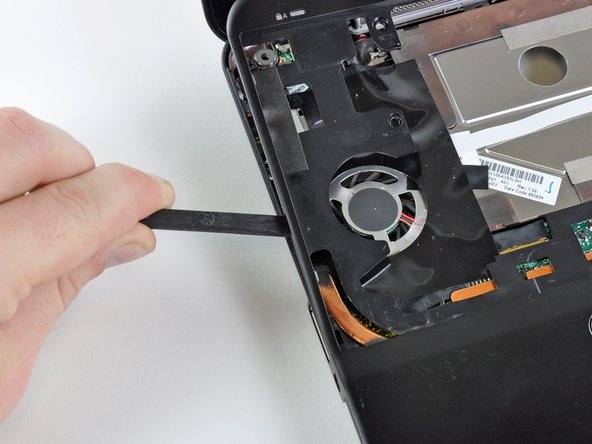
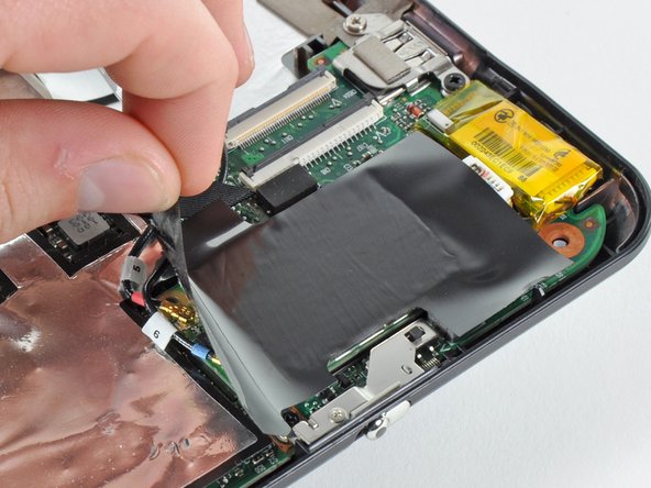
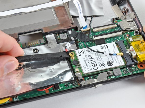
    • Carefully lift the heat sink off the face of the motherboard and de-route the curved section from next to the fan.

    • Before reinstalling the heat sink, be sure to apply a new layer of thermal paste to the CPU. We have a thermal paste guide that makes it easy.

    • Only apply a new layer of thermal paste to the face of the CPU. The CPU is the large processor located closest to the fan.

  24. 这个步骤还没有翻译 帮忙翻译一下

    : 步骤 24 中的图像 1,2 : 步骤 24 中的图像 2,2
    • If present, carefully remove the large piece of black adhesive film covering the Wi-Fi board.

  25. 这个步骤还没有翻译 帮忙翻译一下

    : 步骤 25 中的图像 1,2 : 步骤 25 中的图像 2,2
    • Use the flat end of a spudger to pry both antenna connectors up from their sockets on the Wi-Fi board.

  26. 这个步骤还没有翻译 帮忙翻译一下

    : 步骤 26 中的图像 1,1
    • If present, remove the pieces of tape securing the Wi-Fi antenna cables to the upper case.

  27. 这个步骤还没有翻译 帮忙翻译一下

    : 步骤 27 中的图像 1,1
    • If present, carefully remove the large piece of black adhesive film from the area surrounding the fan.

  28. 这个步骤还没有翻译 帮忙翻译一下

    : 步骤 28 中的图像 1,1
    • If present, remove the several pieces of black cloth tape securing the cables to the upper case near the fan.

  29. 这个步骤还没有翻译 帮忙翻译一下

    : 步骤 29 中的图像 1,2 : 步骤 29 中的图像 2,2
    • Use the flat end of a spudger to disconnect each of the following connectors from their respective sockets:

    • Speaker cable

    • Microphone cable

    • Fan cable

    • Power cable

    • Display data cable

    • Push the connectors out of their sockets parallel to the face of the motherboard toward the display assembly. Do not lift up on the cables as you disconnect them, especially the display data cable, as their sockets may break off the motherboard.

  30. 这个步骤还没有翻译 帮忙翻译一下

    : 步骤 30 中的图像 1,1
    • If present, peel back the strip of white cloth tape highlighted in red to reveal a display screw.

  31. 这个步骤还没有翻译 帮忙翻译一下

    : 步骤 31 中的图像 1,1
    • Remove the single 5 mm Phillips screw securing the right display hinge to the lower case.

  32. 这个步骤还没有翻译 帮忙翻译一下

    : 步骤 32 中的图像 1,1
    • Remove the two 5 mm Phillips screws securing the left display hinge to the lower case.

  33. 这个步骤还没有翻译 帮忙翻译一下

    : 步骤 33 中的图像 1,2 : 步骤 33 中的图像 2,2
    • Lift the display out of the lower case, minding any cables that may get caught.

终点

3等其他人完成本指南。

一条评论

This was really helpful to me. My Mini's screen suddenly popped off on one side. After running through this process I found that both screws on one hinge and one screw on the other had come out. It seems someone forgot to put Lock Tite on them! Within less than an hour the machine was back to its usual self. Thanks!

jim989 - 回复

添加评论

浏览统计数据:

过去 24 小时: 0

过去 7 天: 6

过去 30 天: 11

总计 5,124