跳转到主内容

Repair Speaker Connection to Logic Board

I truly hope someone can help. I've carefully made it through the replacement of my internal HD per iFixit instructions. However, at step 25 (removing speaker connection) the connector on the logic board separated. Is there any way to repair this connection without taking this to an expensive repair shop?

Thank you!! / Curtis
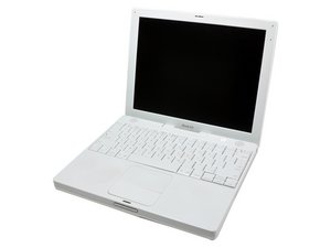
已回答! 显示答案 我也有这个问题

这是一个好问题吗?

得分 2
4条评论

Majesty, thank you for the quick response. I may live without the onboard speakers. Do you know if the headphone jack is affected without this connector? It appears to be a separate circuit.

完成的

I dont think it is, you should be fine if you can live without the speakers. You can always get a USB audio interface or buy some nice speakers to hook up to your output. No problem by the way, thats what we're here for.

完成的

I have some soldering experience in tight spaces but these pads are about 700um each with maybe 500um between pads. That's way beyond my capabilities for sure. In fact, a low powered microscope would really help! I wonder if the pencil tip soldering iron mentioned in your link would really work in this situation? More like a needle tip and then the concept of solder droplet size comes into play, etc. I'm really impressed if that's possible!

I've picked up some conductive polymer ink and have added an extremely small amount to the pads and I'm letting it dry now with the connector in place (hopefully). Once that is dried (and not knowing really how much made adhesive-like contact with the connector, I'm going to add a drop of silicone outside the contact area to help secure the connector to the logic board. I'll let you all know how this conductive ink method works if you are interested.

完成的

Yes, of course. Keep me posted, I can learn a thing or two from your experience.

完成的

添加一条评论

2个答案

已选择的解决方案

If the connector has separated from the logic board, you need to get that re-soldered on and unless you have the necessary equipment and technical know-how, you would have to take the board to a qualified technician.

这个答案有帮助吗?

得分 2

6条评论:

I contacted our local Mac repair center and was told this is end of story. No way to solder the tiny contacts. Only can be done at manufacturing with the solder flow used in the process.

So, my question turns to are you aware of any kind of heat resistant glue I could use to connect this to the board? The contacts are still in good condition and line up perfectly into the micro sized solder joints. All I really need is to hold the connection pins onto those contacts and a tiny drop of heat resistant 'rubber cement' on the back would be worth a try. (nothing to lose, only possibly gain the speakers)

完成的

I don't think glue is a good Idea as it is not a good conductor and will block any necessary contact. I would venture to say that maybe a little heat from a heat gun can "reflow' the solder, but I'm not particularly experieced at this level of repair.

完成的

The speaker out jack still works allowing the use of external speakers. As to repairing the board I am including a link to a similar problem with I think a good answer. Ralph

Separated speaker socket from LB; computer won't sleep

完成的

+ Ralph---Still meed a edit feature for comments!

完成的

I agree Rj, I have had my bouts with writing, deleting, and re-writing comments.

完成的

显示更多的1条评论

添加一条评论

If there's still a bit of solder on the four small audio solder pads on the logic board yes you can resolder the socket in place using a pencil soldering iron like the Weller WM 120. There are two methods to restore the speakers functionality when the audio socket was pulled from the logic board. If the socket still has the four pins under it then you can resolder them if not then you can solder four wires directly to the pads then solder or connect them to the speakers wires.

这个答案有帮助吗?

得分 2

3条评论:

Great Suggestions. +

完成的

Yes, there were still solder depressions created by the horizontal pins from the connector. If my current scenario doesn't work, I'll give the soldering method a shot. Could you tell me, if attempt to solder the connector with pins back in place, do I assume correctly that I would need to remove the logic board and apply the heated solder tip to what would be the backside (opposite side) from the connector? There isn't any space on the connector side. (i.e. heat through the board pins)?

完成的

Yes it's better to remove the logic board from the metal frame so you'll have more space to work. Then reinstall the socket exactly as it was on the logic board with the four pins over the four solder pads then briefly apply the solder iron tip over each pin, I use a magnifying glass to align the pins over the pads before soldering. You may apply just a little solder flux on the pins for a better solder job.

完成的

添加一条评论

添加你的答案

crtolson 将永远感激不已
浏览统计数据:

过去 24 小时: 0

过去 7 天: 0

过去 30 天: 2

总计 2,945