简介
Teardown/Disassembly of the Tascam DR-40 released back in 2012.
Side Note: Ignore the watermark on the images. I forgot to disable it when I exported the photos from Lightroom.
你所需要的
-
-
Ensure you have a clean, static-free working environment. Some parts in the Tascam DR-40 are sensitive and could be easily damaged.
-
-
-
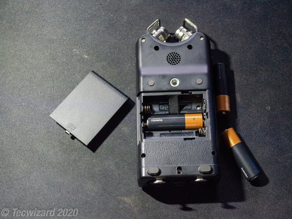
Open the rubber flap on the right side of the device and push the SD Card in until it clicks and pops out, allowing you to remove it.
-
Open the back cover and remove the batteries from the device.
-
-
-
There are a total of 10 Phillips Screws that hold both halves of the housing together.
-
-
-
Use a Phillips #1 Screwdriver to remove the screws from the housing. Keep in mind that there are 3 screws that are different lengths as mentioned in the last step.
-
-
-
You should be left with 8 screws. Take note of the two bottom screws that came from the screw holes near the speaker.
-
Now take note of the silver screw above the bottom left black screw that came from the battery housing.
-
This screw is longer than the other 5 silver screws so make sure to organize your screws accordingly.
-
-
-
Gently pull up on the rear housing to seperate it.
-
Two battery contacts will separate from the case as you pull up on the housing as shown in the video.
-
-
-
Use a flathead screwdriver to gently pry the negative battery contact away from the casing if it gets suck on the plastic nub.
-
Once the casing is free gently lift it up until the two battery contacts are free from the rear housing.
-
-
-
-
Use a flathead screwdriver to gently pry up on the rear speaker. The speaker is glued into place with double-sided tape so take your time.
-
Once the speaker is removed the rear housing can be set aside.
-
-
-
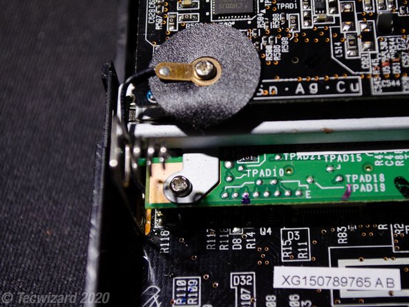
There are 7 Screws holding down the three different circuit boards. On the top you have the three screws holding down the sound board to the logic board with the screw on the left holding a grounding cable that's soldered to the main board.
-
On the Logic board there is a single screw that's holding it to the front housing.
-
Finally at the bottom you have 4 screws holding down the XLR Jacks and the main board to the front housing.
-
-
-
Remove the screw holding down the logic board to the front housing followed by the screw connecting the grounding cable to the sound board.
-
Once the screws are removed the only thing keeping the two boards in place is the white connector at the bottom of the logic board.
-
Gently pry up on the logic board to disconnect it from the main board.
-
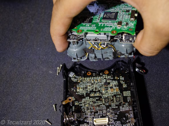
Once the two boards are free, fold it over the microphone assembly to gain access to two additional screws.
-
-
-
Use a Phillips #0 Screwdriver to remove the two screws holding the microphone assembly to the front housing.
-
Once the two screws are removed, gently lift up on the assembly. It should come out as one piece with the logic and sound boards attached.
-
-
-
Remove the 2 screws holding down the XLR Assembly to the front housing. (Here I also removed the two screws holding down the main board. You don't have to do this.)
-
Use a flat head screwdriver to unclip the front housing from the XLR Jack assembly. Not much force is needed here.
-
Gently lift up on the assembly until the the pins come out from the connector on the main board. Once removed the assembly can be set aside.
-
-
-
In order to remove the main board from the housing you must remove the EXT IN slider as it in the way and holding the board down.
-
Gently press on the tabs with a flathead screwdriver to pop the slider out of the housing.
-
-
-
Once the slider is removed, gently lift up from the top of the board and pull out to disconnect the Remote Jack from the bottom of the casing.
-
The board should easily come out and can be set aside once removed.
-
-
-
The buttons can be removed as one piece just but pushing them out from the front of the casing.
-
The MODE, QUICK, PB CONT, and MIXER buttons are held in place by plastic pegs and can be removed simply by just prying up on it with a flathead screwdriver.
-
-
-
Separating the two boards is easy. First remove the two remaining screws holding it together.
-
Next, gently lift up at the board until the black connector is disconnected. Once disconnected the Logic Board will come loose from the Sound Board.
-
The metal shielding on the logic board is not held down by anything and can be simply lifted off the logic board.
-
-
-
Disassembling the microphone assembly is easy. Unscrew and remove the 4 brackets holding down the microphone guards.
-
Remove the guards by lifting up on them and sliding them out on both sides. This will reveal two screws holding the two plastic housings together.
-
Remove the two screws and gently separate the two halves of the housing.
-
-
-
Congrats, you successfully disassembled your Tascam DR-40 Field Recorder.
-
Overall the parts are pretty accessible and swapping parts out seem easy enough.
-
However, more complicated repairs like repairing the screen or replacing the speaker/microphones will require more advanced tools such as a good soldering iron that can easily reach the small pads on the circuit boards.
-
To reassemble the Tascam DR-40, follow this teardown in reverse then jump to Step 20.
-


7等其他人完成本指南。

6条评论
Mine will not power on at all even with USB power. IS there any sort of fuse or something?
Annie Uzer - 回复
Sadly I'm no electronics expert or an expert with this device. I created the teardown because I was gonna clean the inside of the plastic screen cover which required full disassembly of the device. I'm sure someone here or on Reddit can be of better help. I would check the contacts for the battery compartment and double check that the Hold switch on the side is OFF. I don't think the device accepts USB Power but I'm not home to test out the theory for myself.
Completed the disassembly trying to identify the reason why mine turns off immediately after I power it on. I will re-assembly and clean some components to see if this fixes it, not an electronics expert so really appreciated the guide. If someone has any other ideas as to what is causing this issue I'll appreciate the help.
I'm not an expert on electronics or this device. Assuming the issue isn't bad batteries then is sounds like a component on one of the boards has failed. I recommend seeking the aid of a professional who has the tools and skills to probe each board and identify the failed component. It could be anything from a bad resistor to a failed chip. You could also try buying a similar device for parts and attempt swapping the various boards until the issue is resolved. You may loose your settings in the process depending on the board. Hope this helps.