简介
A few months ago, we pre-ordered the MicroBot Push, and we’ve been itching to try it out. Due to some manufacturing hiccups, the Push was only shipped out recently – just on time for this month's teardown!
你所需要的
-
-
Removing the 4 Torx screws and 1 regular one beneath the black rubber pad shows us a gearbox, 2 PCBs and a battery
-
-
-
According to its specs, the MicroBot has a battery life of about one year. The battery is rechargeable, using a regular 5V charger with a micro USB connector.
-
Battery charging circuit
-
Charging IC
-
Transistor to control the red and green LEDS next to the USB port, indicating whether or not the battery is fully charged
-
Battery protection circuit
-
These types of ICs are used to “sense” the current
-
When the specified current limit has been reached they trigger a switch that will break the current path to the battery. The switch that is triggered in this case is a Dual N-Channel Enhancement Mode Power MOSFET, in this case the 8205A
-
-
-
-
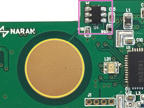
The capacitive touch button and matching circuitry (marked in red)
-
The big gold circle you see in the middle of the PCB is a capacitive touch button. It’s simply an exposed piece of copper
-
The TTP223B chip, this chip is a one-key touch pad detector that can detect the touch of a human finger on the touch pad. It does this by using the “Frequency Change” method
-
-
-
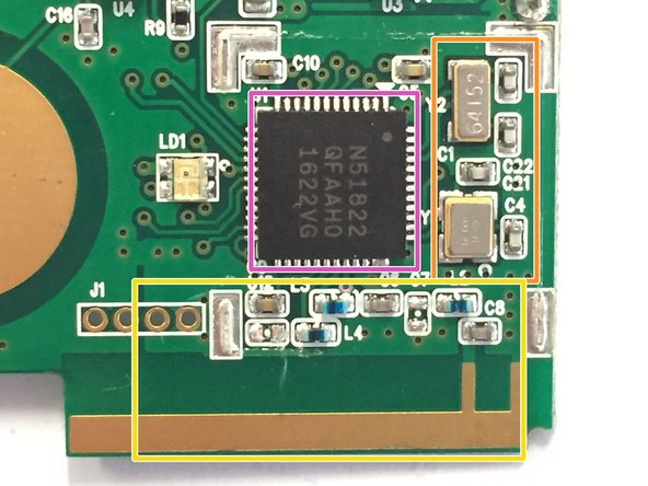
The bluetooth chip and antenna (I had to remove a metal shield to reveal the chip;)
-
The bluetooth chip, in this case the nRF51822 Nordic Semiconductors (It’s a 2.4GHz ultra low-power bluetooth chip built around a 32-bit ARM® Cortex™ M0 CPU)
-
To the right of the nRF51822, you can see two oscillators, one 16MHz and one 32.768kHz (marked in orange), which generate the clock waveforms for the CPU
-
On the bottom (marked in yellow) you see the antenna circuitry and the PCB antenna itself. As you can see, they did not use a balun chip, but instead created a matching network using some capacitors and inductors.
-
-
-
This circuit is located on the back of the PCB
-
I could not trace back the datasheets of the actual components used, but after probing the upper IC with an oscilloscope I noticed that this is also a voltage regulator. This one boosts the voltage from 2.5 volts back to 4 volts to power the motor and the motor controller
-
Motor driver
-
-
-
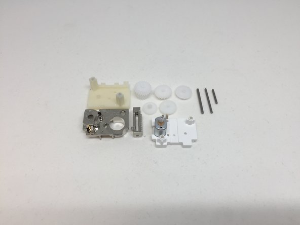
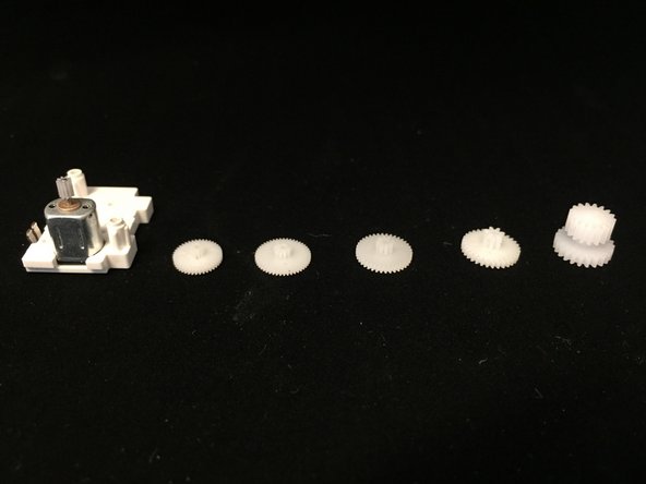
Opening up the gearbox was fairly simple: I just had to remove two screws to expose the gears and the motor
-
If we count all teeth of the gears we come up with a speed reduction of 948.41
-