简介
Before there was the Switch, the Nintendo Game Boy line of handheld game consoles was the king of the streets. 30 years later, the original model still holds a special place in the hearts of on-the-go gamers. In honor of its 30th anniversary, we decided to travel back in time to see what made the original Game Boy tick.
Want more teardowns? Follow us on Instagram, Twitter, and Facebook for all the latest teardown and repair news. For news delivered, sign up for our newsletter.
你所需要的
-
-
While it wasn’t the first handheld game console to hit the market, the Game Boy popularized the category and kickstarted the portable gaming industry.
-
Tech Specs:
-
4.19 MHz 8-bit processor
-
8 KB of RAM
-
2.6" 160x144 STN LCD display
-
-
-
Denoted by model number DMG-01 (which stands for Dot Matrix Game), the Game Boy can be powered by either four AA batteries or an AC power adapter, the latter of which has unsurprisingly disappeared into the clutter abyss.
-
If you're wondering, that 800 number does still call Nintendo's support line, just in case you ever need some help with your retro handheld.
-
-
-
The case is held together by six tri-point Y1 screws. Even back in 1989, Nintendo thought traditional screws might be too easy for us tinkerers. Fortunately, our Mako Driver Kit comes with the necessary bit.
-
Nintendo was at least nice enough to include an indentation for our driver to nicely fit into within the battery compartment.
-
-
-
-
The LCD display is attached to the circuit board with clips and a couple of screws. Unfortunately, the display's cable is soldered to the board, making display replacements a bit tricky.
-
The speaker, which is typically a modular component in many devices today, is also soldered to the board. Fortunately, it's just two wires with simple solder points.
-
-
-
We hope you enjoyed this trip down memory lane!
-
Now if you'll excuse us, we're going to put this thing back together and enjoy some Super Mario Land 2.
-


8条评论
We truly have come a long way =) Thanks for the share.
2020. Thanks
Great tear down, thank you for highlighting the chips.
Great tear down! I want to use an old gameboy to frame it like this:
https://images.squarespace-cdn.com/conte...
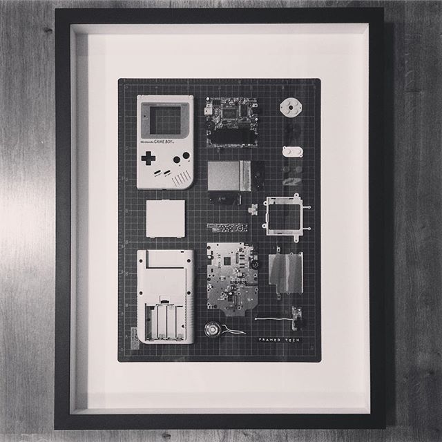
Regarding Step 7, it says here: “The LCD display is attached to the circuit board with clips and couple of screws. Unfortunately, the display's cable is soldered to the board.”
My question: what’s the best and cleanest way to remove the LCD display? It doesn’t have to function again afterwards, it just needs to look as nice and cleanly taken apart as possible :)
If anyone has a good hint, please let me know! Thanks!
Fanning a soldering iron back and forth on the soldered connection should do the trick!
Magnifico questo teardown, mi ricorda i tempi in cui da piccolo smontavo ogni apparecchio elettronico che avevo per pura curiosità di vedere come fosse fatto dentro. :D
Awesome teardown. This helped alot.