
‘Twas the night before Christmas, when all over the house
The lights were flashing like crazy, thanks to Carl Friedrich Gauss.
Here at iFixit, we’re natural tinkerers, tweakers, and fixers. Many of us spend our free time on side projects and activities which could only be described to normal people as “crazy” or “insane”. Mine happens to bring Christmas cheer to local family and friends, so I thought I’d share it with all of you this year as well. And it probably falls into the “crazy” category.
The Christmas lights I’ve put up at my parents house for the past few years would make Clark Griswold proud. Yes, it’s one of those displays where the lights flash in sync with the music.
Now I could have gone out and purchased an off-the-shelf solution (like a Light-O-Rama system), but that’s just not how I roll. It would be way more fun to build this thing myself! So back in fall of 2008, armed with nothing more than a bit of money and a half-complete bachelors degree in Computer Engineering, I set off to build my own animated Christmas lights show.
Like all good engineers, I started by doing research. Lots and lots of research. I had plenty of experience building digital systems that ran on DC power at a friendly 5 volts, but controlling 32 channels of Christmas lights running on 120V AC power was new to me, and the last thing I wanted to do was burn down my parents’ house for Christmas.
After reading a few scattered articles I’d found around the web, I stumbled upon the Do It Yourself Christmas forums. DIY Christmas is a place for light show tinkerers to meet up, share experiences, and provide tips on everything from hardware controllers to sequencing music. These were my kind of people!
I opted to design my own controller rather than get in on a group-buy for an existing design. To save time, I decided to piggy back on the FPGA board I’d already learned how to use in school. I just needed to design a peripheral board that would let me control 32 channels of lights.
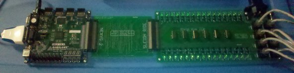
The FPGA board on the left receives lighting information from a computer via the serial cable for each of the 32 channels. Each channel is represented by a single byte, where 0-255 represents 0% – 100% brightness. After decoding each channel, it controls 32 outputs which travel over to the board on the right. For each of the 32 channels, the board on the right will show its status on an LED and send it out to the yard over a standard Cat 5 Ethernet cable.
That bridge board in the middle? That’s a painful reminder that no matter how rushed you are to get something done, you should always double check things you use from the internet. I happened to find a PCB design for the large connector that someone had been kind enough to post on their blog, which saved me a lot of design time because that connector has 50 pins on it. Unfortunately, the original author had connected all the pins backwards, so pin 1 was actually pin 50, pin 2 was actually pin 49, and so on. That bridge board was something I threw together quickly to reverse all the pins on the connector.
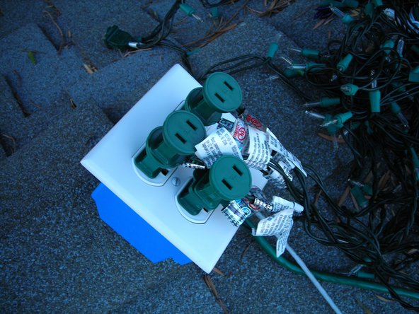
Out in the yard, there are 8 electrical gang boxes, each of which has four outlets. These four outlets are individually controlled by the four channels that come in over the Ethernet cable. The power itself doesn’t come over the Ethernet cable, though. The Cat 5 wire inside is so tiny that it can’t handle powering the lights, so there’s a small board inside each gang box called a solid state relay.

The control signal over Ethernet is just 5V and a couple milliamps. This needs to switch 120V at several amps, depending on how many strands of lights I have plugged into the outlet. This calls for a relay, which is basically just an electronically-controlled switch. When my low-voltage control electronics trigger the relay, it opens the floodgates for the wall socket power to come through. This lets you control big-power things with small-power electronics.
An important part of this setup are those tiny square black chips in the picture. Those are opto-isolators, and they’re pretty clever little chips. The last thing I want is a stray power surge in my high-voltage circuits to get into my low-voltage circuits, because that would most certainly destroy a lot of expensive electronics. Those chips allow you to keep the two sides safely isolated. When the low-voltage side triggers the opto-isolator, it turns on a tiny LED inside the chip. That LED triggers a photodetector, which turns on the high-voltage side of the circuit. The two circuits are linked, but completely electrically isolated from each other. Cool beans!
The last piece of the puzzle is sequencing the lights to music. Thanks to the hard work of a fellow DIYer, Vixen is freely available software for doing just that . It even has a plug-in system if you want to make it run your own custom-built controllers, like I did.
It’s been a lot of work getting the display up and running. Sourcing parts, designing logic boards, writing embedded control software, plugging in all the lights, and sequencing the show certainly takes quite a time commitment, but seeing the smiles on peoples faces when they watch it makes all the work well worth the effort every year.
From our epilepsy-inducing houses to yours, have a very happy holidays and a wonderful new year!
But I heard him exclaim, as he drove out of sight
Merry Christmas to all, and to all some bright lights.


0条评论