当前版本的文档还未经巡查,您可以查看最新的已查核版本。
你所需要的
-
-
这个步骤还没有翻译 帮忙翻译一下
-
Remove the following 4 screws:
-
Three 1.8 mm Phillips #00 screws securing the headphone jack and GPS antenna to the rear case. Note the order in which you remove the screws, as the left one has a slightly larger head.
-
One 3.8 mm Phillips #00 screw in the plastic loop near the headphone jack.
-
-
这个步骤还没有翻译 帮忙翻译一下
-
Remove the four Phillips #00 screws securing the volume and mute switch.
-
The mute switch assembly screws should be tightened with the switch in the off position. Check the protrusion of the switch when turned on, since it may not stick out far enough to operate if the switch assembly is incorrectly positioned. (Check the gap between the switch frame and the bezel (white gap showing between the two screws near the 6). The screw on the far right is slightly longer than the other 3 screws. When reassembling the phone, keep this in mind.
-


119等其他人完成本指南。

10条评论
I managed this in about an hour to fix a broken "volume up button" and combined with replacing a broken ringer/mute switch. Thanks for the guide!!!
Two very minor comments to consider:
- Step 19 indicates three 1.8mm screws and one 3.8mm. In my 3G i found the middle "1.8mm screw" is actually smaller. Hopefully this helps someone who didn't notice that on the way out...
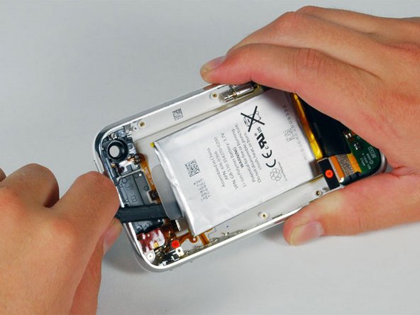
- Step 14 doesnt mention the flexible clip that is attached to the logic board and fits under the bezel on the right hand side near the dock connector end. Most people will find it anyway, but it might help those like me (who are pushing the limits of their technical skills) to note the preferred method for handling this. I just moved the logic board towards the opposite side and popped it out with a screw driver...
These are only minor points but overall i found the guide to be excellent and much easier to follow than anything else i found including you tube videos etc.
来自 Paul 的话:
I managed this in about an hour to fix a broken "volume up button" and combined with replacing a broken ringer/mute switch. Thanks for the guide!!!
Two very minor comments to consider:
- Step 19 indicates three 1.8mm screws and one 3.8mm. In my 3G i found the middle "1.8mm screw" is actually smaller. Hopefully this helps someone who didn't notice that on the way out...
- Step 14 doesnt mention the flexible clip that is attached to the logic board and fits under the bezel on the right hand side near the dock connector end. Most people will find it anyway, but it might help those like me (who are pushing the limits of their technical skills) to note the preferred method for handling this. I just moved the logic board towards the opposite side and popped it out with a screw driver...
These are only minor points but overall i found the guide to be excellent and much easier to follow than anything else i found including you tube videos etc.
i broke the little tab in the bottom of the main board, now my network service is always low, its connected to the signal right? is it okay to solder a piece of wire there so that it can touch the metal bezel?
来自 pgatj 的话:
I replaced this part successfully but my phone still thinks it's in headphone mode. There is obviously no lint in a new jack so plugging/unplugging a set of headphones isn't working. What else would cause my phone to only have sound with headphones plugged in?
Did you finally get it fixed. I don't want to do all this and still have the dreaded "headphones" when none are connected.
Ditto! I'm a month out of warrantee-- went to the Apple store (twice!), where they blew out every atom of lint in the headphone jack. Went home only to see the phone had once again reverted to thinking headphones were plugged in.
来自 Scott 的话:
Did you finally get it fixed. I don't want to do all this and still have the dreaded "headphones" when none are connected.