简介
Prereq for removing logic board.
你所需要的
-
-
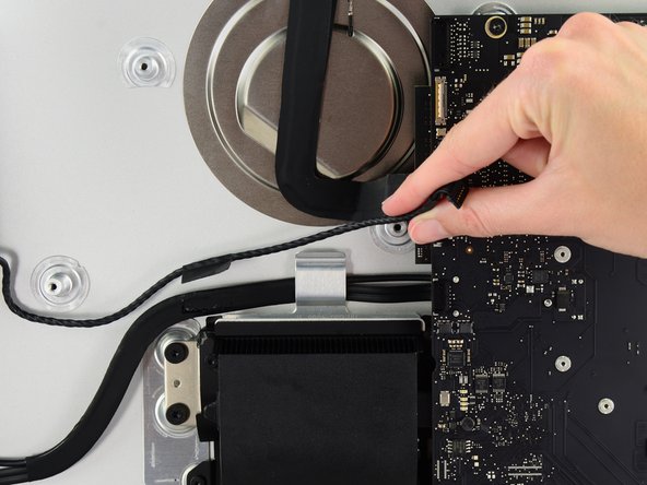
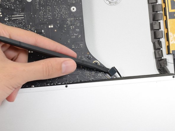
Push on each side of the left speaker cable connector with the tip of a spudger and gently walk it out of its socket.
-
-
-
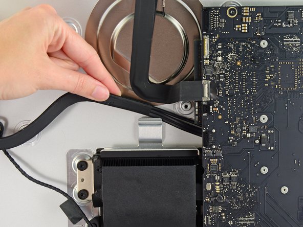
If necessary, use a pair of tweezers to gently peel the tape securing the left speaker cable to the SATA data/power cable.
Actually i didn't get why should i unstick the tape which gum up left speaker cable to the SATA data/power cable. It's gonna be hard to bond the tape again cause it looses the clue ability. I can definetely claim that there is no need to touch the tape.
I too can say that there was no reason to remove the tape.
Agreed. I completed the repair without removing the tape.
phil -
-
-
-
-
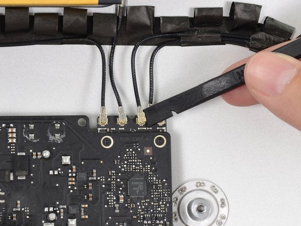
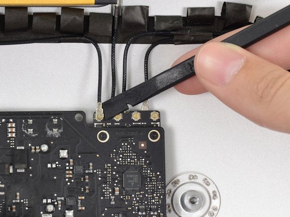
Use the flat edge of a spudger to disconnect each of the four antenna connectors from the AirPort/Bluetooth card.
i found it helpful to use the flat end of the spudger under the cable near the connector and gently wiggle the spudger until the cable was disconnected.
Tim Telcik - 回复
Agreed, I broke one connector. The airport seems to work anyway. But what to do to fix it? Change the airport card or try to weld it again?
I mark each cable tip with a different colored sharpie and then take a Pic. This gives me the order and the angle of orientation in order to reconnect these pesky connectors.
OK, so when did you remove the RIGHT speaker? Suddenly it is not in the photos. I s there anything besides it's plug to remove?
-
-
-
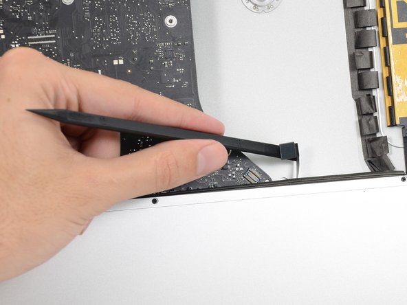
Use the flat edge of a spudger to pry the headphone jack cable connector from its socket on the logic board.
The photo in Step 51 shows the right speaker missing, however there is no step prior for removing the right speaker.
Hence, refer to this other guide to remove the right speaker *before* Step 51.
Tim Telcik - 回复
Its there! Step 28 & 29 is the removal, the left one doesn’t need to be removed.
Dan -
-
-
-
Remove the following screws securing the exhaust duct to the rear enclosure:
-
Two 6.3 mm T8 screws
-
Two 4.7 mm T8 screws
A T9 bit fits and grips the screws tight enough to make it easier to work with the deep 4.7mm screw.
-
-
-
Remove the four 7.2 mm T10 screws securing the logic board to the rear enclosure.
So a major problem for me here — my iMac (purchased 2018 ) has a solid circular fastener where the lower left T10 screw should be. So I think I’m dead in the water as far as getting the logic board off to put the new RAM in. I can’t see how people can insert the ram from behind without seeing it or being able to get two fingers to the tabs. I’m so frustrated with the design of this computer.
That’s a new one on us! We’d love to see a photo. Any chance it’s a tamper-proof sticker hiding the head? You may also be able to turn it with a set of pliers if you can get a decent grip, just be careful not to bump any board components!
It’s a tamper proof sticker. I started to peel it up, but it was just easier to press the screwdriver bit in.
as an update, these are now T8 screws
cwaldrip -
-
-
-
Tilt the top of the logic board away from the rear enclosure.
-
Lift the logic board straight up and out of the iMac.
This is the trickiest part of the whole operation. It took me a solid half hour to get the logic board out. I’m sure it would be easier a second time, because there’s not many delicate components around the USB/Internet sockets, so you can be a little more assertive with it than I felt comfortable doing.
i found the logic board kept snagging on the USB connectors poking through the exterior case. Wiggle the logic gently to extract..
Tim Telcik - 回复
Take out the two screws that hold down the right speaker, and push it up a little, before removing the logic board. It makes things a lot easier.
Also: there’s a cable on the right side of the logic board that isn’t called out. Nor are the two HDD cables that plug into the underside of the logic board.
-


To reassemble your device, follow these instructions in reverse order.
To reassemble your device, follow these instructions in reverse order.


A step is entirely missing here – removing the right speaker cable connection from the logic board and also removing the right speaker casing (all the pictures below show it already having been removed). You actually don't need to entirely remove the right speaker to get the logic board out but you will need to remove its screws and lift it slightly. And you will need to remove its plug from the motherboard but that's not hard and it looks identical to the left speaker plug/socket.
biscuit - 回复
This does need adding to the guide if anyone from ifixit sees this!
Alan Digby -