With the hinge free to move, the iMac will be unbalanced and hard to work on. Repairs can be completed as shown, but are faster and easier with an iMac service wedge.
Before beginning any work on your iMac: Unplug the computer and press and hold the power button for ten seconds to discharge the power supply's capacitors.
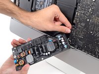
Be very careful not to touch the capacitor leads or any exposed solder joints on the back of the power supply. Only handle the board by the edges.
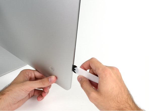
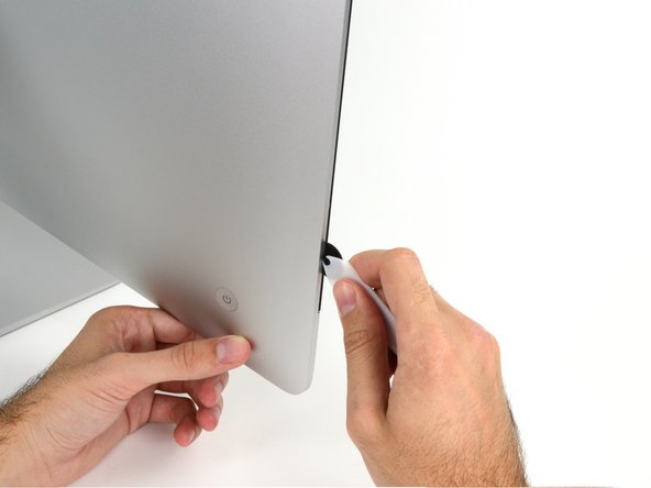
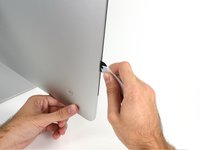
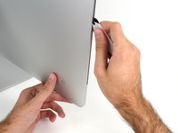
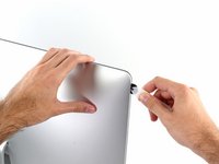
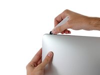
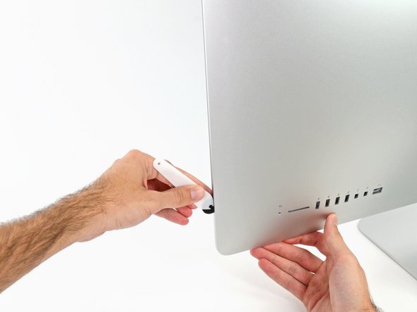
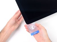
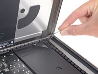
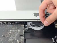
Starting on the left of the display, near the power button, insert the iMac Opening Tool into the gap between the glass panel and the rear enclosure.
The hub on the iMac Opening Tool will keep you from pushing the wheel in too far. If using a different tool, insert no more than 3/8" into the display. Otherwise, you risk severing antenna cables and causing serious damage.
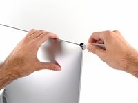
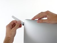
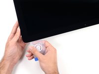
Be gentle! The glass may crack if pried too much. Use a hairdryer to heat the edges and loosen the tape if the room temperatures are low.
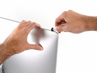
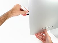
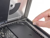
You may want to run the tool back and forth through what you've already cut a few times, to ensure you get as much of the adhesive separated as possible.
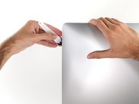
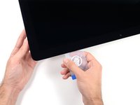
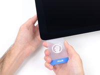
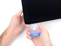
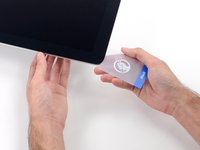
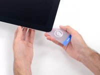
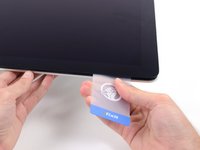
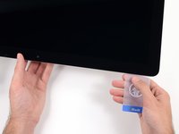
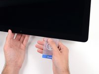
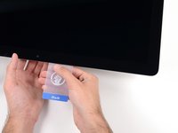
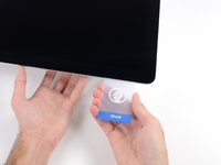
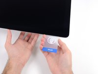
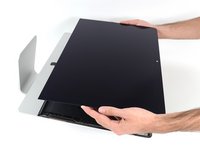
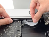
While the opening tool cut most of the adhesive, the display will still be slightly adhered to the case. A plastic card will be necessary to free up the last of this adhesive.
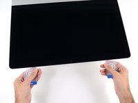
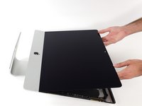
Set the iMac face-up on a table.
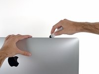
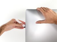
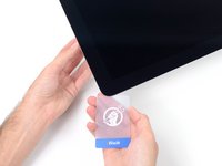
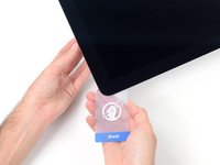
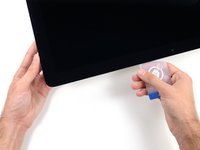
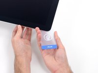
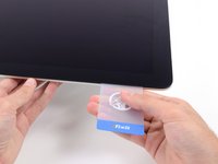
Starting from the top right corner of the iMac, wedge a plastic card between the display and frame.
Be careful not to insert the plastic card more than 3/8", or you may damage internal components.
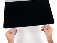
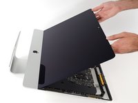
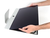
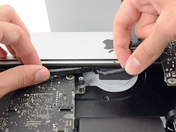
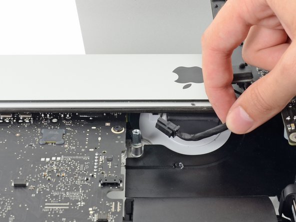
While holding the display up with one hand, use the other hand to unplug the display power cable. Make sure that you pull the cable out from the plastic tab, and not by pulling on the color wires.
Lift the display up enough to have easy access to the connector, but not so much that you stretch the cables and stress their connections (about 8").
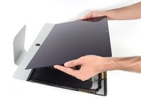
At this point there is still a strip of adhesive along the bottom of the display, that will hold the display to the frame like a hinge. You can loosen this adhesive by working the display up and down a few times.
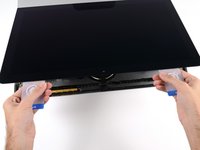
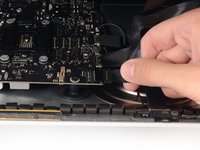
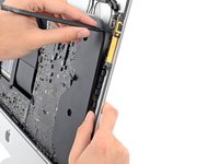
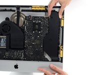
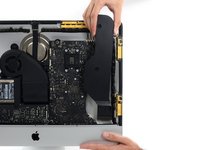
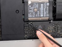
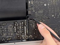
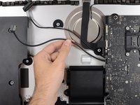
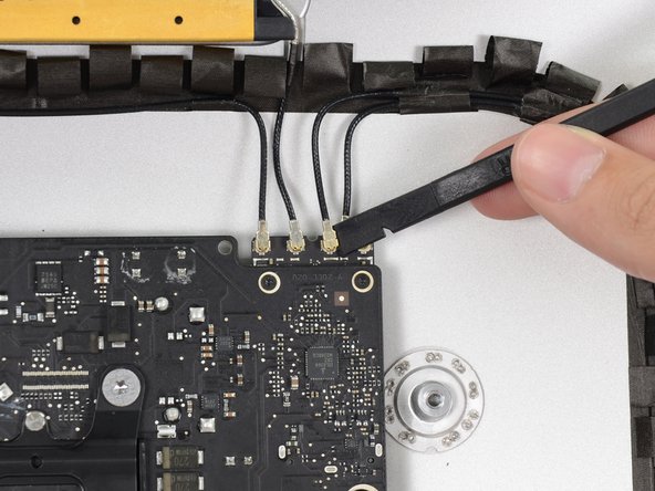
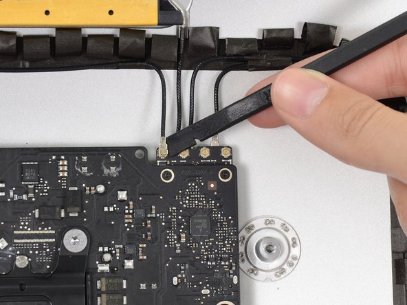
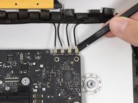
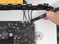
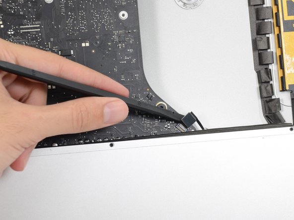
Use a spudger to loosen the right speaker cable's connector from its socket on the logic board.
It is useful to push downward on both short sides of the connector to "walk" it out of its socket. Be careful with the corners of the connectors, they can be easily broken off.
Pull the connector downwards to remove it from its socket.
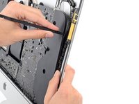
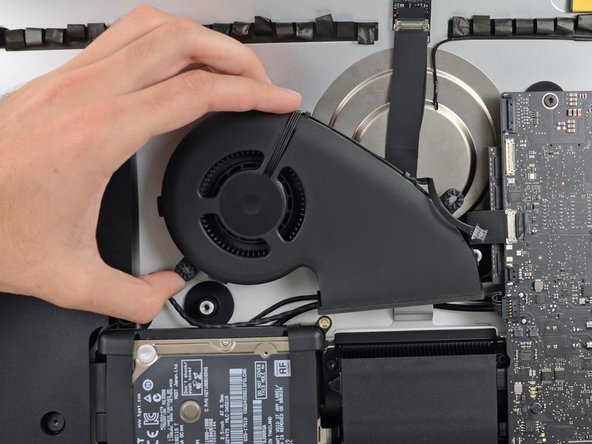
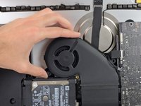
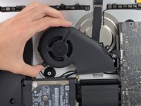
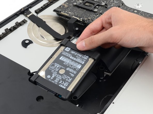
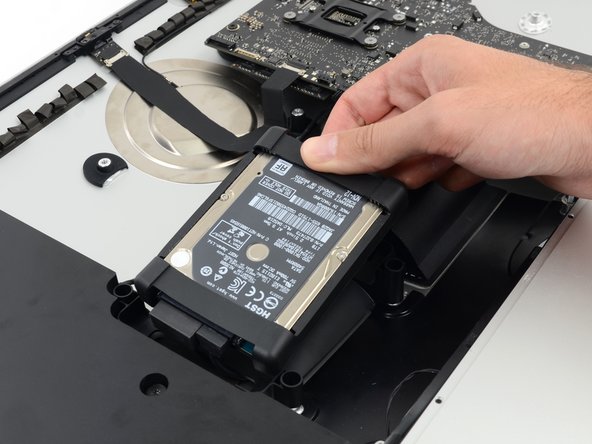
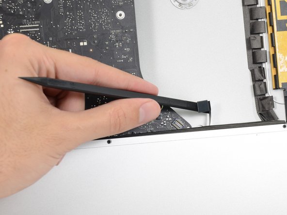
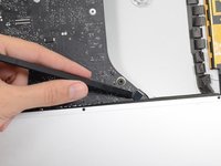
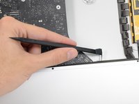
Pull the right speaker straight up about an inch, toward the top of the iMac.
Lift the right speaker straight up and remove it from the iMac. This may take some force, both hands and rocking the speaker right and left to get it out.
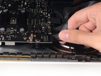
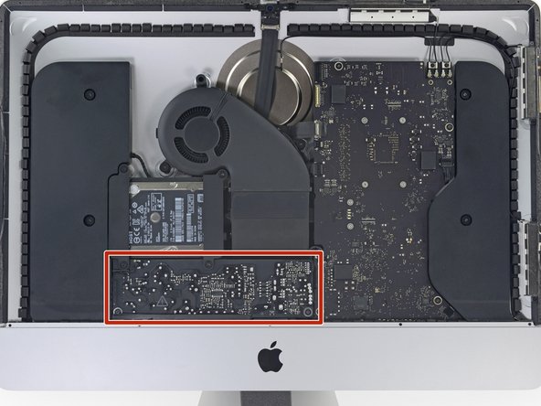
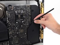
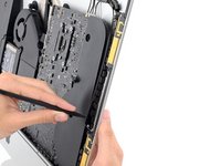
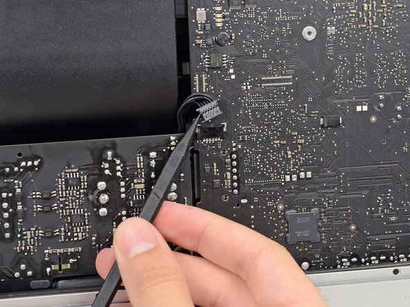
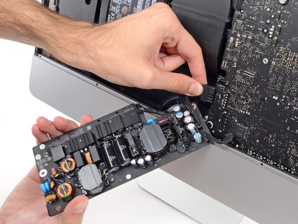
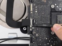
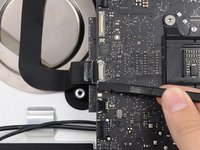
The next few steps bring your hands close to the exposed face of the power supply. Do not touch the face of the power supply to avoid a high voltage shock from the many large capacitors attached to the board.
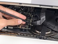
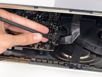
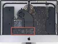
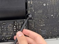
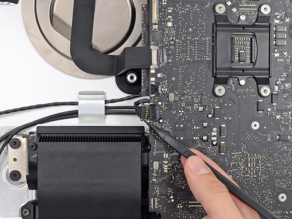
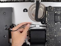
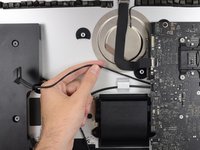
Use the tip of a spudger to push each side of the power button cable connector and gently "walk" it out of its socket.
When working on the power supply, be very careful not to touch the capacitor leads or any exposed solder joints on the back of the power supply. Only handle the board by the edges.
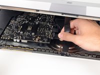
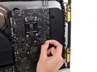
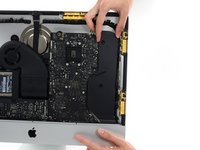
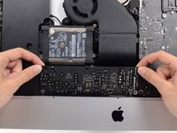
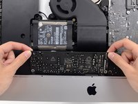
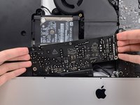
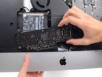
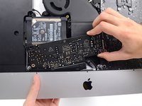
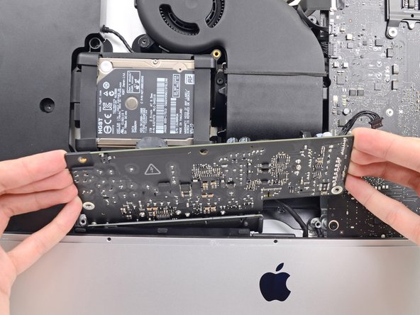
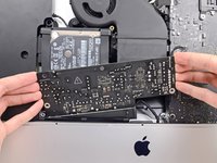
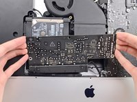
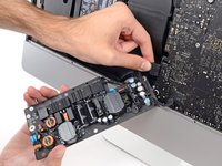
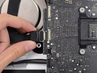
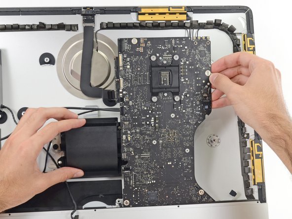
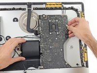
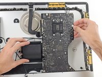
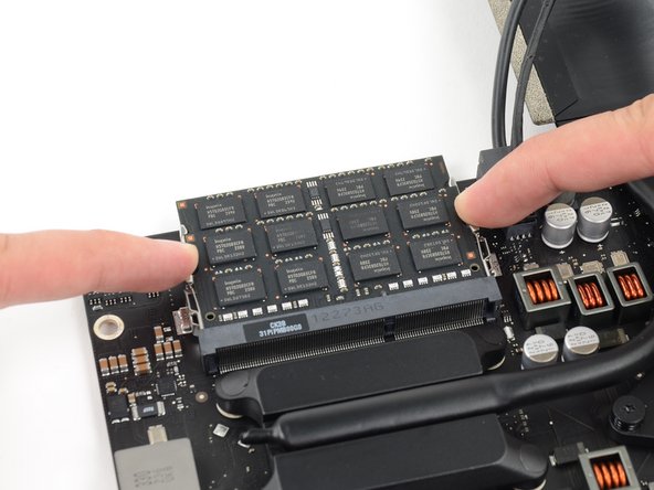
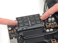
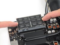
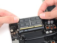
Tilt the top of the logic board away from the rear enclosure.
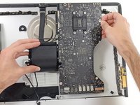
Lift the logic board straight up and out of the iMac.
Be careful not to snag the board on any of the rear case's screw posts.
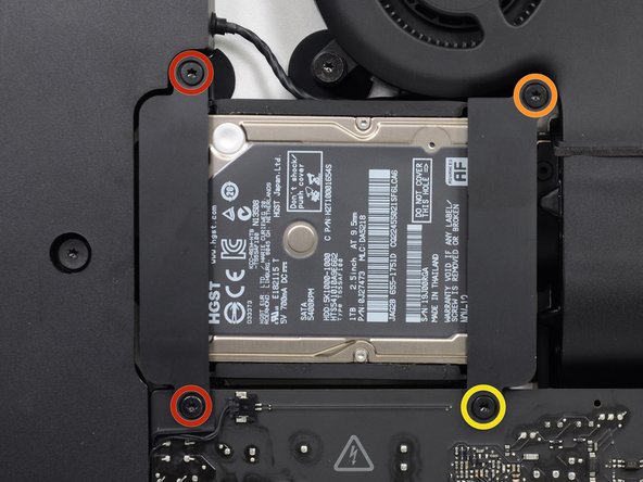
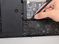
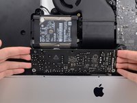
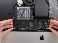
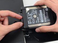
The I/O boards at the bottom of the logic board will be the greatest challenge. It is recommended to pull gently to avoid any damage.
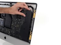
During reassembly of the logic board, pay attention to the position of the I/O connectors. When the board is back in the case, insert a USB or Thunderbolt cable into one of the connectors to align it perfectly.
I used the iMac Opening Tool just as shown starting in step 2 to separate the tape. DISASTER! The screen cracked! I used the tool slowly and carefully and despite this, the screen cracked. I should have simply used a guitar pick. That said, I decided to see if I could upgrade the 8GB RAM to 16GB RAM WITHOUT removing the logic board all performing all of these steps. I found I could simply remove the FAN assembly as shown in step 43. This makes enough room to reach behind the logic board and unclip the 2 memory modules. I installed 2 8GB modules (1600MHz DDR3L SO-DIMM PC12800 204 Pin) without much trouble. I used a plastic stick to reach behind the logic board and unclip the existing memory modules, then carefully inserted the new ones and clipped them into place. This is much easier than performing all of these steps.
Hi There, I am interested in going in and upgrading my RAM to 16. Did you do all the steps ups to 43? Remove the power supply? Did you remove the hard Drive? I take it you had to do step 53 as well and remove the iSight camera cable first? I may try it your way, I hate to have to unplug 98% of everything to do this. Thanks for the tip.
I added extra RAM by following step 1-23, then skipping to do just 41-43 and then reach the RAM from the back of the logic board. It was difficult to reach but possible.
Thanks for the tips here.I used a guitar pick and some credit cards as suggested, and to worked fine. I also followed Mikael’s suggestion :
“I added extra RAM by following step 1-23, then skipping to do just 41-43 and then reach the RAM from the back of the logic board. It was difficult to reach but possible.”
which worked fine for me too. Thanks for the suggestion. Have ordered tools & adhesive from ifixit anyway cos the site & its community showed me how to do it all anyway