跳转到主内容

当前版本的文档还未经巡查,您可以查看最新的已查核版本

你所需要的

  1. , 检修门: 步骤 1 中的图像 1,1
    • 松开检修门上唯一一颗十字螺丝。

    • 这个螺丝固定着检修门。

    • 从iMac上移开检修门。

  2. , 玻璃面板: 步骤 2 中的图像 1,2 , 玻璃面板: 步骤 2 中的图像 2,2
    在这个步骤中使用的工具:
    Heavy-Duty Suction Cups (Pair)
    $14.95
    购买
    • 玻璃面板固定在前外壳上,周围有十四个磁铁固定。

    • 在玻璃面板的对角线上吸上两个吸盘。

    • 要使用吸盘吸的牢固,首先将吸盘可以活动的把手移动使其与玻璃面板平行。 在轻轻地将吸盘保持在玻璃上的同时,抬起活动手柄直到与另一个手柄平行。

    • 如果您的吸盘无法吸上,尝试使用温和溶剂例如Windex来清洁玻璃面板和吸盘。

  3. : 步骤 3 中的图像 1,1
    • 小心,竖直的从iMac上提起玻璃面板。

    • 玻璃面板周围有几个定位销。 为了避免将玻璃面板上的这些针脚弄坏,请务必在拆卸过程中竖直向上拉动。

    • 在重新安装之前,请务必仔细清洁LCD和玻璃面板的内部面板,因为当显示屏打开时,你不想被任何指纹或灰尘所困扰。 将玻璃平面放置在干净的铝箔表面上是保持清洁的最好方法。

  4. , 外圈: 步骤 4 中的图像 1,1
    • 移除将后壳与外圈固定的12颗螺丝。

    • 8颗13mm T8 梅花螺丝。

    • 4颗25mm T8 梅花螺丝。

  5. : 步骤 5 中的图像 1,1
    • 断开麦克风线缆连接插头,如果有必要的话移走胶带。

    • 要确保挡板正常,请确保将麦克风电缆和连接器插入相机板旁边的空白处。

  6. 这个步骤还没有翻译 帮忙翻译一下

    : 步骤 6 中的图像 1,2 : 步骤 6 中的图像 2,2
    • When reassembling the bezel:

    • be sure to tuck the microphone cable and connector into the void next to the camera board.

    • Gently guide the microphone connector and cables through the ±1in long slot at the right of the iSight camera. Once the bezel is properly assembled, gently push the microphone connector and cable into the bezel through that slot.

  7. 这个步骤还没有翻译 帮忙翻译一下

    : 步骤 7 中的图像 1,2 : 步骤 7 中的图像 2,2
    • After removing the front bezel, you need to remove the 8ea 12mm T8 screws around the perimeter of the LCD

    • Rotate the iMac so the TOP EDGE is facing you and GENTLY lift the LCD up about 75mm (3in) and prop up the LCD with something NON CONDUCTIVE.

    • Lifting the LCD in this way exposes the rear of the PSU to allow access to the PSU connector. When the imac is connected to the mains (even if switched OFF) there is MAINS VOLTAGE on this board

  8. 这个步骤还没有翻译 帮忙翻译一下

    : 步骤 8 中的图像 1,3 : 步骤 8 中的图像 2,3 : 步骤 8 中的图像 3,3
    • REMEMBER - there is MAINS voltage on the PSU so use extreme caution

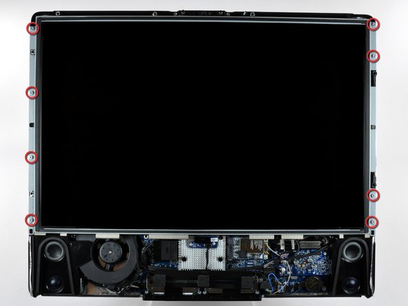
    • Use the chart provided as a reference and test the various voltages with your meter being sure to restrict the probes to the 10 solder joints on the PSU connector shown within the BLUE rectangle. Shorting any part of the PCB will almost certainly cause damage to the imac

    • All voltage measurements are taken with PIN 1 as reference (Marked with the YELLOW square). Pin 1 is marked on the board by a dot and is the right hand pin when viewed as shown in photos

    • STANDBY means system connected to mains outlet but imac turned off - Diagnostic LED 1 will be illuminated on logic board

    • Pin 5 is the PSU enable line - Logic board pulls this line low (0V) to enable PSU (probably via a resistor)

    • Pin 4 voltage varies according to the PSU temperature and is inversely proportional to PSU temperature. Higher Temp = Lower Voltage. My measurement was taken at around **24 Deg Celsius.

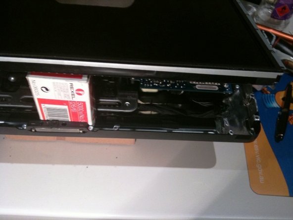
    • Reassemble your iMac in reverse order. When lowering the LCD ensure you don't crimp or crush the LCD back-light cables

终点

20等其他人完成本指南。

Richdave

于04/09/10注册

32,051 声望

创作了30篇指南

团队

Master Techs Master Techs 的会员

Community

322 名成员

创作了2,520篇指南

10条评论

Something I don't get…

I'm investigating on my mid2007 iMac power problems and I don't get the same results of voltage as in this article. In my case, number 9 is at around 12V and number 8 is at 0V.

Is my PSU really faulty or there might be some other PSU models?

Vince1286 - 回复

I've got the same results as you. Wondering if we have the wrong ps model, despite being what iFixit recommends and sells. Very odd.

Matthew Zeller -

i have the same issue. Do we have the wrong power supply or the wrong voltage chart?

Tim Bowman - 回复

Have also the same, maybe the table here is wrong. What kind of problems does your mac have?

Marvin Marik -

Hello, I get 0 volt readings on both pins 4 & 8 on Standby. Does this mean the PSU is bad? If I had a 3rd arm to press the power button I could test other pins. Thank you!

Charles - 回复

添加评论

浏览统计数据:

过去 24 小时: 1

过去 7 天: 9

过去 30 天: 56

总计 50,287