be sure to tuck the microphone cable and connector into the void next to the camera board.
Gently guide the microphone connector and cables through the ±1in long slot at the right of the iSight camera. Once the bezel is properly assembled, gently push the microphone connector and cable into the bezel through that slot.
De-route the left speaker cable from the channel in the CPU fan. Continue completely de-routing the cable through the undersides of the IR board and heat sink.
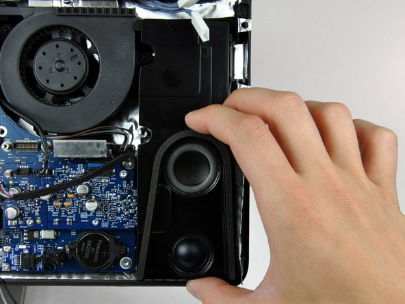
Remove the single 28 mm T10 Torx screw securing the left speaker to the rear case.
Lift the left speaker up and out of the rear case. Don't try to slide the speaker out, since there is a plastic mounting pin under the top end of the speaker housing that holds it in place.
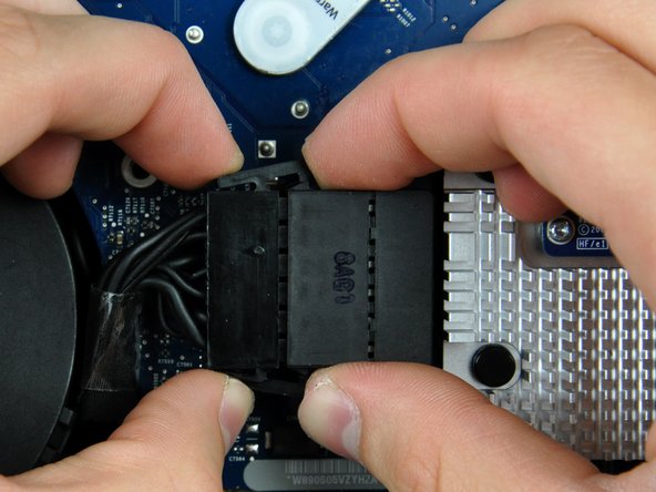
Disconnect the SATA data cable from the logic board by carefully pulling it straight away from its socket.
The SATA connector on most iMacs tends to stick in its socket on the logic board. If you are having trouble disconnecting the SATA cable, insert a metal spudger or any other thin tool into the gap between the SATA connector and its socket and twist the spudger's shaft to safely separate the two pieces.
Disconnect the DC-in cable by simultaneously depressing both locking arms and pulling its connector away from the socket on the logic board.
After both locking arms pass their retaining tabs, it is helpful to push them toward the left edge of your iMac with one hand while pulling on the body of the connector with your other hand.
Use the flat end of a spudger to pry the optical drive cable clip up off the optical drive connector.
Lift the optical drive cable clip off the logic board.
During reinstallation, be sure the two raised bumps on the lower edge of the optical drive cable clip lock into the two voids on the underside of the optical drive socket.
Lift the microphone cable connector straight up out of its socket on the audio board.
During reinstallation, ensure that the mic cable runs between the ODD fan and the board support. If the cable runs on the wrong side of the support, the cable will be too short to plug in.
Remove the following 13 screws securing the logic board to the rear case:
Six 7.2 mm coarse-thread T10 Torx.
Two 6.8 mm T8 Torx. When reinstalling these two screws, don't overtighten them, as the plastic tabs they hold down are thin and brittle, and can crack.
Lift the logic board out of the rear case, minding any cables that may get caught.
If the front edge of the logic board, under the RAM sockets, won't pull up, it's sticking on the three plastic mounting pins in the rear housing under this edge. Use a spudger under the front edge of the RAM sockets to gently push up on this edge until it clears these mounting pins.