跳转到主内容

当前版本的文档还未经巡查,您可以查看最新的已查核版本

你所需要的

  1. , 打开挡板门: 步骤 1 中的图像 1,2 , 打开挡板门: 步骤 1 中的图像 2,2
    • 拧下两个巩固挡板的十字螺丝

    • 从iMac上移除挡板

    • 在开始工作前,拔下电源线然后长按电源建20-30秒来让电容放电

  2. , 前面板: 步骤 2 中的图像 1,1
    • 移除这四颗螺丝

    • 三个六毫米 T8 梅花螺丝

    • 一个八毫米 T8 梅花螺丝

  3. : 步骤 3 中的图像 1,2 : 步骤 3 中的图像 2,2
    • 让iMac正面朝上,放在水平地平面上

    • 同时提起iMac的前面板

    • 用拇指按住 内存臂并推住 iMac。

    • 用食指将前面板上的板向自己方向拉。

    • 用食指向上提起前面板。

    • 一旦小板离开了 内存 臂,将前面板的下边缘抬起,你会发现刚好足以离开后壳的底部边缘。

  4. : 步骤 4 中的图像 1,3 : 步骤 4 中的图像 2,3 : 步骤 4 中的图像 3,3
    • 将iMac立起来

    • 将塑料卡向上插入靠近后壳顶部的通风槽的一角。

    • 将卡推向 iMac 的顶部以松开前面板闩锁。

    • 将前面板拉离后壳。

    • 对前面板板的另一侧重复此过程。

    • 可能需要在卡的顶部贴几层胶带,以帮助松开闩锁。

    • 如果挡板无法松开,请尝试将下边缘按回后壳并重复此打开过程。

  5. : 步骤 5 中的图像 1,1
    • 平放你的iMac

    • 从下边缘提起前挡板并将其旋转远离 iMac 的其余部分,注意可能被内存壁卡住。

    • 将前挡板放在 iMac 的其余部分。

  6. : 步骤 6 中的图像 1,1
    • 如有必要,取下缠绕在麦克风和摄像头电缆上的聚酰亚胺胶带(可以扔掉它)。

  7. : 步骤 7 中的图像 1,2 : 步骤 7 中的图像 2,2
    • 断开摄像头和麦克风电缆。

  8. , 屏幕: 步骤 8 中的图像 1,1
    • 剥下下方的 EMI 屏蔽层。

    • 只需要从三个侧面向上剥离屏蔽层。 让它连接到显示器上。

    • 将 EMI 屏蔽贴在显示器上以防止它挡路。

  9. : 步骤 9 中的图像 1,2 : 步骤 9 中的图像 2,2
    • 卸下将显示数据电缆固定到逻辑板上的两颗 4.8 毫米 T6 梅花螺钉。

    • 抓住显示数据线连接器的黑色卡舌,将其直接向上拉离主板。

  10. : 步骤 10 中的图像 1,1
    • 把iMac 上的逆变器电缆从左侧拉出。

    • 将逆变器电缆连接器从主板上的插座中垂直向上拉出。

  11. : 步骤 11 中的图像 1,1
    • 从显示屏的两个垂直边缘剥下铝制 EMI 胶带。

    • 在重新组装过程中,在将显示器放入 iMac 后壳之前,使用几条小胶带将 EMI 屏蔽沿显示器脚印的左右边缘固定好会很有帮助。

  12. : 步骤 12 中的图像 1,2 : 步骤 12 中的图像 2,2
    在这个步骤中使用的工具:
    TR10 Torx Security Screwdriver
    $5.99
    购买
    • 让EMI防护罩从显示器上垂下来。

    • 卸下将显示屏固定到后壳上的四颗 8 毫米和 2 毫米粗头粗螺纹 T10 螺钉。

    • 这些螺丝是凹进去的,所以像这样的细螺丝刀对于拆卸是必不可少的。螺丝刀对这种应用来说往往太短。

    • 强烈建议使用磁化螺丝刀,以免螺丝掉入 iMac。

  13. : 步骤 13 中的图像 1,1
    • 从显示器的下边缘提起,并将其拉向自己,以剥去连接在其上边缘的EMI防护罩。

    • 注意任何在拆除过程中可能被夹住的电缆。

  14. 这个步骤还没有翻译 帮忙翻译一下

    : 步骤 14 中的图像 1,1
    • Remove the 30 mm T10 Torx screw securing the left speaker to the rear case.

  15. 这个步骤还没有翻译 帮忙翻译一下

    : 步骤 15 中的图像 1,1
    • Remove the 17 mm T10 Torx screw from the right speaker.

  16. 这个步骤还没有翻译 帮忙翻译一下

    : 步骤 16 中的图像 1,1
    在这个步骤中使用的工具:
    Metal Spudger
    $2.99
    购买
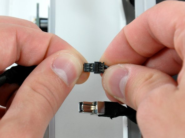
    • Pull the SATA data cable connector away from its socket on the logic board.

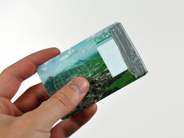
    • The SATA connector on most iMacs tends to stick in its socket on the logic board. If you are having trouble disconnecting the SATA cable, insert a metal spudger or any other thin tool into the gap between the SATA connector and its socket and twist the spudger's shaft to safely separate the two pieces.

  17. 这个步骤还没有翻译 帮忙翻译一下

    : 步骤 17 中的图像 1,1
    • Disconnect the CPU fan by pulling its connector up off the logic board.

  18. 这个步骤还没有翻译 帮忙翻译一下

    : 步骤 18 中的图像 1,1
    • Disconnect the hard drive power cable by pulling its connector up off the logic board.

  19. 这个步骤还没有翻译 帮忙翻译一下

    : 步骤 19 中的图像 1,1
    • Use the flat end of a spudger to pry the AirPort Extreme antenna connector up off the AirPort Extreme card.

  20. 这个步骤还没有翻译 帮忙翻译一下

    : 步骤 20 中的图像 1,1
    • If necessary, remove any tape covering the left speaker cable.

  21. 这个步骤还没有翻译 帮忙翻译一下

    : 步骤 21 中的图像 1,2 : 步骤 21 中的图像 2,2
    • Lift the left and right speakers out of the rear case.

    • The speaker cables are still attached to the logic board.

    • The right speaker cable may be routed under the power button cable or the CPU fan cable (or both). If so, disconnect both cables by pulling their connectors away from the face of the logic board.

  22. 这个步骤还没有翻译 帮忙翻译一下

    : 步骤 22 中的图像 1,1
    • Disconnect the speaker cable connector by pulling its connector away from the socket on the logic board.

    • Pull the connector parallel to the face of the logic board.

  23. 这个步骤还没有翻译 帮忙翻译一下

    : 步骤 23 中的图像 1,1
    • Pull the power button cable connector up off its socket on the logic board.

  24. 这个步骤还没有翻译 帮忙翻译一下

    : 步骤 24 中的图像 1,1
    • Disconnect the ambient light sensor by pulling its connector up off the socket on the logic board.

  25. 这个步骤还没有翻译 帮忙翻译一下

    : 步骤 25 中的图像 1,1
    • Disconnect the following four connectors by pulling them straight away from their sockets:

    • Camera cable.

    • Microphone cable.

    • Optical drive fan cable.

    • Hard drive fan cable.

  26. 这个步骤还没有翻译 帮忙翻译一下

    : 步骤 26 中的图像 1,1
    • Disconnect the optical drive thermal sensor cable from its socket on the logic board.

  27. 这个步骤还没有翻译 帮忙翻译一下

    : 步骤 27 中的图像 1,1
    • Remove the two 7 mm fine thread T10 Torx screws securing the optical drive clip to the logic board.

    • Remove the optical drive clip.

  28. 这个步骤还没有翻译 帮忙翻译一下

    : 步骤 28 中的图像 1,2 : 步骤 28 中的图像 2,2
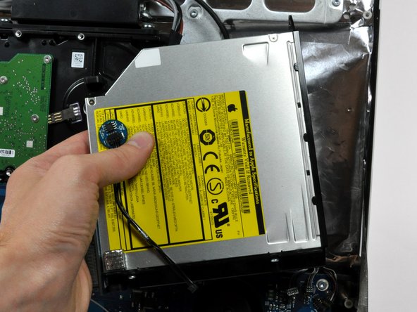
    • Squeeze the two optical drive bracket ears together while pulling the drive up toward yourself.

    • It may be helpful to hold the logic board down near the optical drive connector when pulling the drive toward yourself to avoid both components lifting together.

    • Pull the optical drive away from the side of the rear case and remove it from the iMac.

    • If your optical drive is particularly stubborn to remove, try the method used in the optical drive guide from the A1144 G5 iMac.

  29. 这个步骤还没有翻译 帮忙翻译一下

    : 步骤 29 中的图像 1,1
    • De-route the bundle of power supply cables from behind the hard drive bracket.

    • Some logic boards can be removed without taking out the hard drive.

  30. 这个步骤还没有翻译 帮忙翻译一下

    : 步骤 30 中的图像 1,1
    • Press the hard drive bracket down to free it from the rear case, then rotate the top of the drive toward yourself.

    • Pressing the top of the hard drive bracket down to release it from the rear case requires a substantial amount of force, so we recommend laying your iMac stand-side down on a table to avoid knocking it over.

  31. 这个步骤还没有翻译 帮忙翻译一下

    : 步骤 31 中的图像 1,1
    • Lift the hard drive (with cables attached) straight up off its lower pins and remove it from the rear case.

    • Be mindful of the hard drive cables, as they may catch on the logic board during removal.

  32. 这个步骤还没有翻译 帮忙翻译一下

    : 步骤 32 中的图像 1,1
    • Unplug the power supply cable bundle from the logic board by simultaneously depressing the locking mechanism (toward yourself) with a spudger and pulling the connector away from its socket.

    • The locking mechanism faces the rear case.

  33. 这个步骤还没有翻译 帮忙翻译一下

    : 步骤 33 中的图像 1,1
    • Remove the following six screws securing the logic board to the rear case:

    • Three fine-thread 7 mm T10 Torx.

    • Three coarse-thread 7 mm T10 Torx.

  34. 这个步骤还没有翻译 帮忙翻译一下

    : 步骤 34 中的图像 1,1
    • Be sure to touch the chassis before proceeding to discharge any static.

    • Grab the logic board from its left edge and rotate it out from the rear case, using your other hand to press the RAM arms in enough to clear the rear case.

    • Be mindful of the ports attached to the rear of the logic board as they may stick to the rear case.

  35. 这个步骤还没有翻译 帮忙翻译一下

    : 步骤 35 中的图像 1,1
    • Pull the logic board straight out of the rear case, minding any cables that may get caught.

    • During reassembly of the logic board, pay attention to the position of the I/O connectors. When the board is back in the case, insert a USB or Thunderbolt cable into one of the connectors to align it perfectly.

  36. 这个步骤还没有翻译 帮忙翻译一下

    : 步骤 36 中的图像 1,1
    • Pull the optical drive fan off the posts protruding from the rear case and lift it out of rear case, de-routing cables as necessary.

  37. 这个步骤还没有翻译 帮忙翻译一下

    : 步骤 37 中的图像 1,1
    • Pull the hard drive fan away from the rear case.

    • If necessary, de-route the cables from under the chassis.

  38. 这个步骤还没有翻译 帮忙翻译一下

    : 步骤 38 中的图像 1,1
    • If necessary, remove the piece of tape holding the AC-in cable under the chassis.

    • Use a pair of tweezers to pull the AC-in cable out from underneath the chassis.

  39. 这个步骤还没有翻译 帮忙翻译一下

    : 步骤 39 中的图像 1,1
    • Disconnect the AC-in connector by simultaneously squeezing the lock mechanism and pulling the connector away from its socket.

  40. 这个步骤还没有翻译 帮忙翻译一下

    : 步骤 40 中的图像 1,1
    • Use a spudger to peel back the EMI tape covering the AC power inlet.

    • It is only necessary to peel the EMI tape off the AC power inlet.

  41. 这个步骤还没有翻译 帮忙翻译一下

    : 步骤 41 中的图像 1,1
    • Remove the four T10 Torx screws securing the AC power inlet and its ground cable to the rear panel.

    • Three course-thread 7mm screws.

    • One fine-threaded 5mm screw.

  42. 这个步骤还没有翻译 帮忙翻译一下

    : 步骤 42 中的图像 1,1
    • De-route the AC-in cable from beneath the chassis.

终点

4等其他人完成本指南。

0条评论

添加评论

浏览统计数据:

过去 24 小时: 2

过去 7 天: 5

过去 30 天: 26

总计 17,667