跳转到主内容

当前版本的文档还未经巡查,您可以查看最新的已查核版本

你所需要的

  1. 这个步骤还没有翻译 帮忙翻译一下

    : 步骤 1 中的图像 1,1
    • Before you work on the computer, unplug the computer and press the power button for 20-30 seconds to drain the stored energy in the power supply.

    • Loosen the two Phillips screws securing the access door to your iMac.

    • These screws are captive in the access door.

  2. 这个步骤还没有翻译 帮忙翻译一下

    : 步骤 2 中的图像 1,1
    • Remove the access door from your iMac.

  3. 这个步骤还没有翻译 帮忙翻译一下

    : 步骤 3 中的图像 1,1
    • Remove the three T8 Torx screws securing the front bezel to the rear panel.

  4. 这个步骤还没有翻译 帮忙翻译一下

    : 步骤 4 中的图像 1,2 : 步骤 4 中的图像 2,2
    • Orient the iMac face-up, on its backside.

    • Use your thumbs to press both RAM arms in past the front bezel for enough clearance to lift it off the rear case.

  5. 这个步骤还没有翻译 帮忙翻译一下

    : 步骤 5 中的图像 1,1
    • While holding the RAM arms in with your thumbs, lift the lower edge of the front bezel enough to clear the rear case.

  6. 这个步骤还没有翻译 帮忙翻译一下

    : 步骤 6 中的图像 1,3 : 步骤 6 中的图像 2,3 : 步骤 6 中的图像 3,3
    在这个步骤中使用的工具:
    Plastic Cards
    $2.99
    购买
    • Re-orient your iMac so it sits upright on the stand.

    • Insert a plastic card up into the corner of the air vent slot at the top of the rear case.

    • Push the card toward the top of the iMac to release the front bezel latch.

    • Pull the front bezel away from the rear case.

    • Repeat this process for the other side of the front bezel.

    • It may be necessary to apply several layers of duct tape to the top of the access card to aid in releasing the latches.

    • If the bezel refuses to release, try pressing the lower edge back onto the rear case and repeat this opening process.

  7. 这个步骤还没有翻译 帮忙翻译一下

    : 步骤 7 中的图像 1,1
    • Lay your iMac stand-side down on a table.

    • Lift the front bezel from its lower edge and rotate it away from the rest of your iMac, minding the RAM arms that may get caught.

    • Lay the front bezel above the rest of the iMac.

  8. 这个步骤还没有翻译 帮忙翻译一下

    : 步骤 8 中的图像 1,1
    • If necessary, remove the piece of kapton tape wrapped around the microphone and camera cables.

  9. 这个步骤还没有翻译 帮忙翻译一下

    : 步骤 9 中的图像 1,2 : 步骤 9 中的图像 2,2
    • Disconnect both the camera and microphone cables.

  10. 这个步骤还没有翻译 帮忙翻译一下

    : 步骤 10 中的图像 1,1
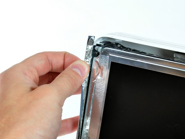
    • Peel back the aluminum EMI shield up off the lower three edges of the rear case.

    • It is not necessary to peel the EMI shield off the display.

    • We found it helpful to tape the EMI shield up against the display to keep it out of the way.

  11. 这个步骤还没有翻译 帮忙翻译一下

    : 步骤 11 中的图像 1,2 : 步骤 11 中的图像 2,2
    • Remove the two 5 mm T6 Torx screws securing the display data cable to the logic board.

    • Using its attached black tab, pull the display data cable connector up off the logic board.

  12. 这个步骤还没有翻译 帮忙翻译一下

    : 步骤 12 中的图像 1,1
    • Pull the inverter cable connector up off its socket on the logic board.

  13. 这个步骤还没有翻译 帮忙翻译一下

    : 步骤 13 中的图像 1,1
    • Peel back the aluminum EMI tape from the two vertical edges of the display.

    • During reassembly, it is helpful to use several small strips of tape to hold the EMI shielding along the left and right edges of the display footprint out of the way before lowering the display into the rear case of your iMac.

  14. 这个步骤还没有翻译 帮忙翻译一下

    : 步骤 14 中的图像 1,2 : 步骤 14 中的图像 2,2
    • Remove the four recessed coarse-thread 7.5 mm T10 Torx screws securing the display to the rear case.

    • These screws are recessed, so a thin screwdriver such as this is essential for removal. Bit drivers tend to be too short for this application.

  15. 这个步骤还没有翻译 帮忙翻译一下

    : 步骤 15 中的图像 1,1
    • Lift the display from its lower edge and pull it toward yourself to peel it off the EMI shield attached to its top edge.

    • Be mindful of any cables that may get caught during removal.

  16. 这个步骤还没有翻译 帮忙翻译一下

    : 步骤 16 中的图像 1,2 : 步骤 16 中的图像 2,2
    • Remove the single 5 mm T6 Torx screw securing the IR board bracket to the logic board.

    • The IR board and cable finger are now free from the logic board and may fall.

    • Remove the IR cable finger and move the IR board, with cable still attached, out of the way.

  17. 这个步骤还没有翻译 帮忙翻译一下

    : 步骤 17 中的图像 1,2 : 步骤 17 中的图像 2,2
    • Remove the single 30 mm T10 Torx screw securing the left speaker to the rear case.

    • Pull the left speaker out of the rear case.

  18. 这个步骤还没有翻译 帮忙翻译一下

    : 步骤 18 中的图像 1,1
    • De-route the left speaker cable along its path across the logic board.

  19. 这个步骤还没有翻译 帮忙翻译一下

    : 步骤 19 中的图像 1,2 : 步骤 19 中的图像 2,2
    • Remove the single 17 mm T10 Torx screw securing the right speaker to the logic board.

    • Lift the right speaker out of the rear case and move it out of the way.

    • Both speakers are still attached to the logic board.

  20. 这个步骤还没有翻译 帮忙翻译一下

    : 步骤 20 中的图像 1,2 : 步骤 20 中的图像 2,2
    • If necessary, lift the IR board cable to free the left speaker cable pinned beneath.

    • Pull the speaker connector toward the top edge of your iMac to disconnect it from the logic board.

  21. 这个步骤还没有翻译 帮忙翻译一下

    : 步骤 21 中的图像 1,2 : 步骤 21 中的图像 2,2
    • Disconnect the CPU fan connector from the logic board by pulling it straight up from its socket.

  22. 这个步骤还没有翻译 帮忙翻译一下

    : 步骤 22 中的图像 1,1
    • Gently lift the CPU fan out of the rear case.

  23. 这个步骤还没有翻译 帮忙翻译一下

    : 步骤 23 中的图像 1,1
    • Disconnect the following connectors from the logic board by pulling them straight up from their sockets.:

    • Ambient light sensor cable.

    • Power cable.

  24. 这个步骤还没有翻译 帮忙翻译一下

    : 步骤 24 中的图像 1,1
    在这个步骤中使用的工具:
    Metal Spudger
    $2.99
    购买
    • Disconnect the hard drive data cable connector from the logic board by pulling it straight up from its socket.

    • The SATA connector on most iMacs tends to stick in its socket on the logic board. If you are having trouble disconnecting the SATA cable, insert a metal spudger or any other thin tool into the gap between the SATA connector and its socket and twist the spudger's shaft to safely separate the two pieces.

  25. 这个步骤还没有翻译 帮忙翻译一下

    : 步骤 25 中的图像 1,1
    • De-route the IR sensor cable from behind the AirPort Express card and set it aside.

  26. 这个步骤还没有翻译 帮忙翻译一下

    : 步骤 26 中的图像 1,2 : 步骤 26 中的图像 2,2
    • Remove two 5 mm T6 Torx screws securing the AirPort/Bluetooth board to the logic board.

    • Lift the AirPort/Bluetooth board up from its left edge to separate it from its socket on the logic board.

    • Lift the AirPort/Bluetooth board from its left edge only. Trying to lift from its right edge may break the connector off the logic board.

  27. 这个步骤还没有翻译 帮忙翻译一下

    : 步骤 27 中的图像 1,2 : 步骤 27 中的图像 2,2
    • Use the flat end of a spudger to pry both antenna cables up off the AirPort/Bluetooth board.

    • This step need not be done. Simply lay the card over the side.

  28. 这个步骤还没有翻译 帮忙翻译一下

    : 步骤 28 中的图像 1,1
    • Disconnect the camera board cable connector from the logic board by pulling it straight away from its socket.

  29. 这个步骤还没有翻译 帮忙翻译一下

    : 步骤 29 中的图像 1,1
    • Disconnect the optical drive fan cable connector from the logic board by pulling it straight away from its socket.

  30. 这个步骤还没有翻译 帮忙翻译一下

    : 步骤 30 中的图像 1,2 : 步骤 30 中的图像 2,2
    • Remove the 7 mm T10 Torx screw securing the optical drive flex cable mounting bracket to the logic board.

    • Remove the flex cable mounting bracket.

  31. 这个步骤还没有翻译 帮忙翻译一下

    : 步骤 31 中的图像 1,1
    • Disconnect the optical drive flex cable from the logic board by pulling it straight up from its socket.

  32. 这个步骤还没有翻译 帮忙翻译一下

    : 步骤 32 中的图像 1,1
    • De-route the hard drive data cable and tuck it under the optical drive to prevent the cable from interfering with future steps.

  33. 这个步骤还没有翻译 帮忙翻译一下

    : 步骤 33 中的图像 1,1
    • Disconnect the hard drive fan connector from the logic board by pulling it straight away from its socket.

  34. 这个步骤还没有翻译 帮忙翻译一下

    : 步骤 34 中的图像 1,2 : 步骤 34 中的图像 2,2
    • Use the tip of a spudger to lift the hard drive and optical drive thermal sensor cables for clearance.

    • Disconnect the optical drive temperature sensor connector from the logic board by pulling it straight away from its socket.

  35. 这个步骤还没有翻译 帮忙翻译一下

    : 步骤 35 中的图像 1,1
    • Disconnect the hard drive temperature sensor connector from the logic board by pulling it straight away from its socket.

  36. 这个步骤还没有翻译 帮忙翻译一下

    : 步骤 36 中的图像 1,1
    • Remove the following screws securing the logic board to the rear case:

    • Four fine threaded 7 mm T10 Torx screws.

    • Three coarse threaded 7 mm T10 Torx screws.

  37. 这个步骤还没有翻译 帮忙翻译一下

    : 步骤 37 中的图像 1,2 : 步骤 37 中的图像 2,2
    • Push the two RAM arms protruding from the access door inward and set them on the lower edge of the rear case to prevent them from getting caught when removing the logic board.

  38. 这个步骤还没有翻译 帮忙翻译一下

    : 步骤 38 中的图像 1,2 : 步骤 38 中的图像 2,2
    • Grab the logic board and pull it toward yourself slightly to separate the jacks from the rear case.

    • Rotate the top of the logic board toward yourself slightly to gain access to the DC power cable connector.

    • Do not completely remove the logic board as the DC power cable connector is still connected to the underside of the board.

  39. 这个步骤还没有翻译 帮忙翻译一下

    : 步骤 39 中的图像 1,1
    • While grasping the logic board with one hand, disconnect the DC power cable connector from the logic board by pulling it straight away from its socket.

    • It may be helpful to wiggle the connector while pulling it.

  40. 这个步骤还没有翻译 帮忙翻译一下

    : 步骤 40 中的图像 1,1
    • Lift the hard drive fan off the plastic posts protruding from the rear case.

    • If necessary, de-route the cables from under the chassis.

  41. 这个步骤还没有翻译 帮忙翻译一下

    : 步骤 41 中的图像 1,2 : 步骤 41 中的图像 2,2
    • Use a pair of tweezers to pull the AC-in cable out from underneath the chassis.

  42. 这个步骤还没有翻译 帮忙翻译一下

    : 步骤 42 中的图像 1,1
    • Disconnect the AC-in cable connector by depressing the lock mechanism while pulling the connector away from its socket.

  43. 这个步骤还没有翻译 帮忙翻译一下

    : 步骤 43 中的图像 1,1
    • Use a spudger to peel back the three pieces of EMI tape covering the AC power inlet.

    • The top and bottom pieces are easy to peel back, but the side piece is easily torn. Be patient while removing the EMI tape.

  44. 这个步骤还没有翻译 帮忙翻译一下

    : 步骤 44 中的图像 1,1
    • Remove the following screws securing the AC power inlet to the rear case:

    • Three T10 Torx screws

    • One T10 Torx screw securing the ground cable.

  45. 这个步骤还没有翻译 帮忙翻译一下

    : 步骤 45 中的图像 1,1
    • De-route the AC-in cable connector from under the chassis and remove the AC power inlet from your iMac.

终点

2等其他人完成本指南。

0条评论

添加评论

浏览统计数据:

过去 24 小时: 2

过去 7 天: 13

过去 30 天: 21

总计 11,026