简介
The motherboard includes all ports except the DC-In board.
你所需要的
-
-
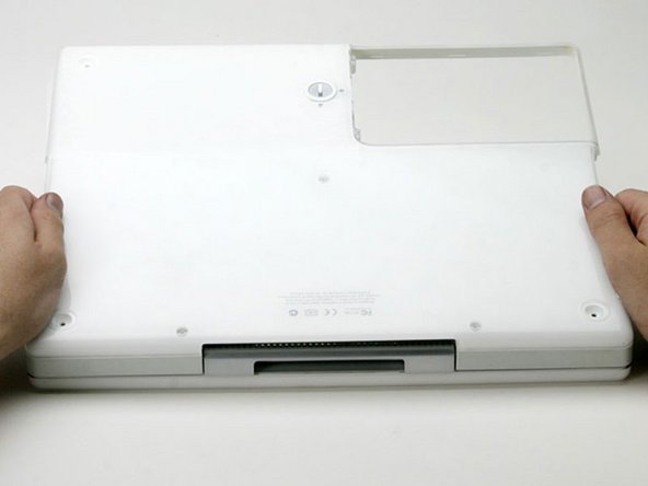
Use a coin to rotate the battery locking screw 90 degrees clockwise.
-
Lift the battery out of the computer.
-
-
-
Pull the keyboard release tabs (highlighted in red) toward you and lift up on the keyboard until it pops free.
-
If the keyboard does not come free, use a small flathead screwdriver to turn the keyboard locking screw 180 degrees in either direction and try again.
-
Flip the keyboard over, away from the screen, and rest it face-down on the trackpad area.
-
-
-
Remove the following 9 screws on the bottom of the computer:
-
Three 3 mm Phillips around the battery compartment.
-
Three 5 mm Phillips on the left and bottom edges.
-
Three 14.5 mm Phillips on the top and right edges (you may have to peel back the foil tape to reveal the screw near the security lock slot).
-
-
-
-
Turn over the computer and open it.
-
Pry up the magnet covering a Phillips screw near the middle of the computer.
Check to see if your model has a screw under the magnet first. If you can lift up the area around the magnet there is no screw to deal with.
-
-
-
Lift the upper case enough to disconnect the blue and white power cable from the logic board.
-
Using your fingernails or a dental pick, carefully pry the connector from its socket.
-
-
-
Remove the following 16 screws:
-
Five 3 mm Phillips (these have smaller heads than the others).
-
Three 5 mm Phillips.
-
Eight 6 mm Phillips.
-
-
-
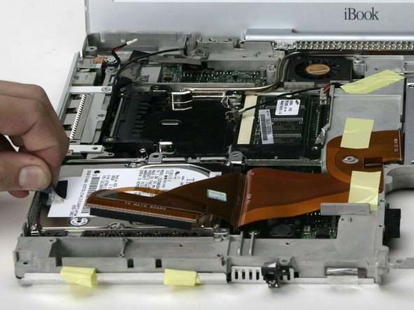
Remove the single strip of tape running across the modem.
-
Remove the single Phillips screw securing the display data cable to the metal framework.
-
-
-
Remove the single Phillips screw to the right of the hard drive connector.
-
-
-
Disconnect the microphone cable from the front, left corner of the logic board.
-
Peel back the black tape and free the microphone cable from the hard drive.
-
-
-
Remove the following 9 screws:
-
Two 3 mm Phillips from the edge of the logic board, near the battery
-
Two 4 mm large head Phillips on the port side, from either corner.
-
One 6 mm Phillips near the sleep light.
-
Two 7.5 mm Phillips securing the battery connector to the metal framework.
-
Two 5 mm Phillips from the logic board. These screws may not be present on some models.
-


To reassemble your device, follow these instructions in reverse order.
To reassemble your device, follow these instructions in reverse order.
8等其他人完成本指南。
附加文件

一条评论
You do need to follow basically this whole procedure for a thermal paste replacement.