当前版本的文档还未经巡查,您可以查看最新的已查核版本。
你所需要的
-
-
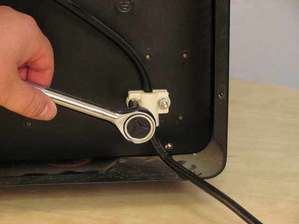
这个步骤还没有翻译 帮忙翻译一下
-
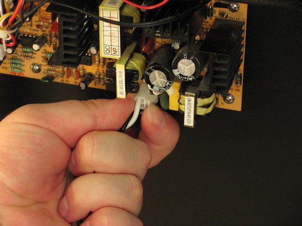
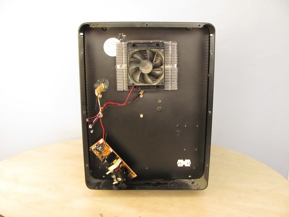
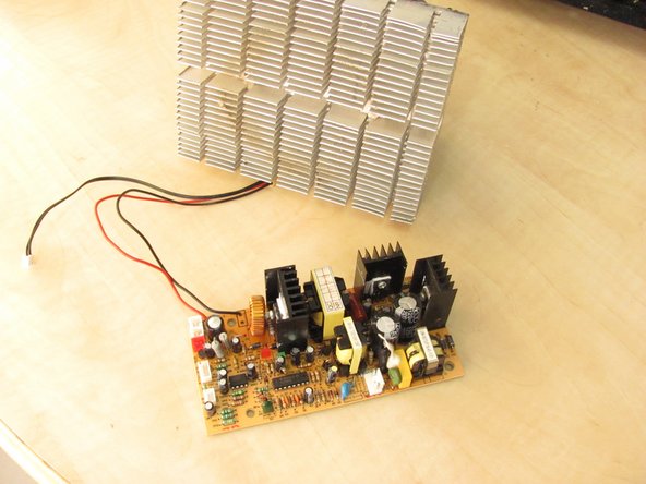
The heat sink and motherboard are removed. Yay!
-
The Vinotemp VT-12TEDi has a very high rate of capacitor failure on the motherboard. Before buying a new motherboard:
-
Check for capacitor failure.
-
Learn how to solder and replace the broken capacitor yourself.
-


9等其他人完成本指南。


4条评论
Hello, I just recently repaired a Vino Temp VT-Humidor for a friend, based upon this article, and wanted to let others know that the VT-Humidor uses the same control board as shown in this repair article. At least the one from 2008 that I repaired does. I found one bad capacitor on the board, which seems to be the biggest failure mode. I am currently working on an Emerson FR966 for the same friend and while the circuit board isn’t exactly the same, it appears to be very similar and the board has the same URL for the mfg. www.hanny.com.cn as the board in the Vinotemp units. Will post again if/when I figure out the problem with the Emerson.
Thank You,
Dave
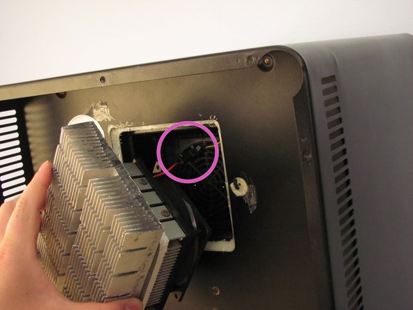
there are 3 connecting device on the board, CN3 FAN, CN4 Fan, and one CDN where do we connect heat fan and cold fan?
The red one is for the internal circulation fan. The other two, I believe, are actually the same (for a two heatsink system). But if you only have one fan, I believe it is hooked up to the top (nearest the corner) connector.
Someplace I have a schematic. My external fan died and I wanted to put the schematic with the unit. Now I can’t find the darned thing. If I could, I’d be able to answer you definitively, but I am almost positive that you can put the heatsink fan on either and you’ll be fine.
Alan -
The red one is for the internal circulation fan. FAN1 and FAN2 are actually the same, so you can plug it into either one. There is a great thread on these controllers here:
https://forum.allaboutcircuits.com/threa...
The tech article really centers around replacing the electrolytic capacitors because they seem to be *very* poor quality. In post #38 there is a link to an excellent thread by another person, but it is all in Spanish:
https://dicasdozebio.com/2013/12/01/1547...
To cut to the chase, however, the author posts two pages of schematics for the board (mind you, there are a few variations, but the general circuit is pretty similar. There isn’t a whole lot to the concept. The links to the schematics are here: