跳转到主内容

VTech Safe and Sound DM111-2 Baby Unit Motherboard replacement Guide

你所需要的

  1. VTech Safe and Sound DM111-2  Baby Unit Motherboard replacement Guide, Baby Unit Motherboard replacement Guide: 步骤 1 中的图像 1,1
    • Along the back of unit there are two 4mm philips head screws towards the bottom of the unit. Start by removing these two screws using your PH0 screwdriver.

  2. VTech Safe and Sound DM111-2  Baby Unit Motherboard replacement Guide: 步骤 2 中的图像 1,2 VTech Safe and Sound DM111-2  Baby Unit Motherboard replacement Guide: 步骤 2 中的图像 2,2
    • Using the plastic spudger gently pry along the middle of the 2 sections of the plastic housing in order to release plastic latches on the inside of the housing.

    • Unlike the parent unit there are no wires across the two housing pieces, so once the latches are undone simply pull it apart without worry of disconnecting anything.

  3. VTech Safe and Sound DM111-2  Baby Unit Motherboard replacement Guide: 步骤 3 中的图像 1,2 VTech Safe and Sound DM111-2  Baby Unit Motherboard replacement Guide: 步骤 3 中的图像 2,2
    • Once apart the motherboard will be exposed with two 4mm phillips head screws near the top and 4 wires leading leading to a circuit board hidden under the motherboard.

    • Remove the two screws near the top of the motherboard.

  4. VTech Safe and Sound DM111-2  Baby Unit Motherboard replacement Guide, Disconnect the microphone: 步骤 4 中的图像 1,2 VTech Safe and Sound DM111-2  Baby Unit Motherboard replacement Guide, Disconnect the microphone: 步骤 4 中的图像 2,2
    • Remove the strip of adhesive tape located under the motherboard.

    • Gently lift the motherboard to expose the inner components.

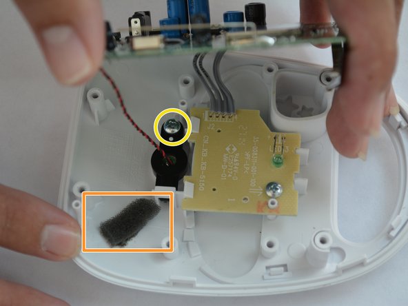
    • Use a spudger to scrape away the adhesive and foam connecting the microphone.

    • Unscrew the 4mm phillips head screw holding the microphone in place.

  5. VTech Safe and Sound DM111-2  Baby Unit Motherboard replacement Guide: 步骤 5 中的图像 1,3 VTech Safe and Sound DM111-2  Baby Unit Motherboard replacement Guide: 步骤 5 中的图像 2,3 VTech Safe and Sound DM111-2  Baby Unit Motherboard replacement Guide: 步骤 5 中的图像 3,3
    在这个步骤中使用的工具:
    Desoldering Pump
    $3.99
    购买
    • Before de-soldering, check to see no scorching or broken connections appear on the wires, power supply jack or antenna.

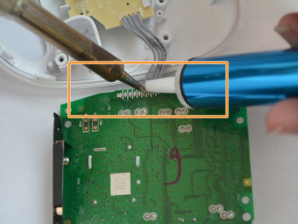
    • De-solder the connections from the motherboard using a soldering iron and a solder sucker.

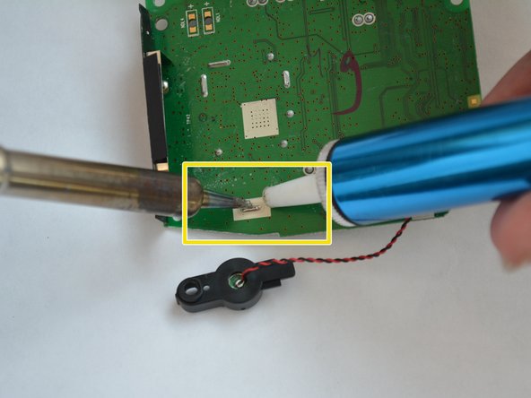
    • De-solder the connections to the microphone, located on the bottom left of the mother board.

    • De-solder the 4 wires connecting the LED board to the motherboard.

    • De-solder the antenna's solder joint, located above the microphone wire connection.

结论

To reassemble your device, follow these instructions in reverse order.

Jean Carlos

于08/31/15注册

201 声望

创作了2篇指南

团队

USF Tampa, Team 6-3, Remmell Fall 2015 USF Tampa, Team 6-3, Remmell Fall 2015 的会员

USFT-REMMELL-F15S6G3

4 名成员

创作了7篇指南

0条评论

添加评论

浏览统计数据:

过去 24 小时: 0

过去 7 天: 0

过去 30 天: 8

总计 899